Feed control lock for hand operated drain cleaner

a technology of hand-operated drain cleaners and lock-type feed control, which is applied in the direction of mechanical control devices, process and machine control, instruments, etc., can solve the problem of tedious drain cleaning operation

Active Publication Date: 2013-06-27
EMERSON ELECTRIC CO
View PDF8 Cites 25 Cited by
  • Summary
  • Abstract
  • Description
  • Claims
  • Application Information

AI Technical Summary

Benefits of technology

[0006]In accordance with yet another aspect, a locking mechanism for a manual or hand operated drain cleaner is provided. The drain cleaner includes a manually operated rotatable drum for holding an elongated flexible cable and rotating a portion of the cable extending from the drum about the cable axis. A handle is adapted to rotatably support the drum. A feed control device is pivotally connected to the handle and movable between a non-actuating position and an actuating position. A driving mechanism engages the cable and allows for axial movement of the cable via rotation of the drum in the actuating position of the feed control device. The locking mechanism comprises a locking member configured to move between a lock position where the feed control device is locked in the actuating position and an unlocked position where the feed control device is freely moveable between the non-actuating position and actuating position. The locking member has a ramp portion adapted to engage one of the handle and the feed control device and maintain the feed control device in the actuating position.

Problems solved by technology

However, this requires one hand to apply the constant pressure and the other hand to rotate the drum.
Because of the constant pressure that has to be applied to the cable feeding device to affect axial movement of the cable, drain cleaners of this type can render a drain cleaning operation tedious.

Method used


Image

  • Feed control lock for hand operated drain cleaner
  • Feed control lock for hand operated drain cleaner
  • Feed control lock for hand operated drain cleaner

Examples


Embodiment Construction

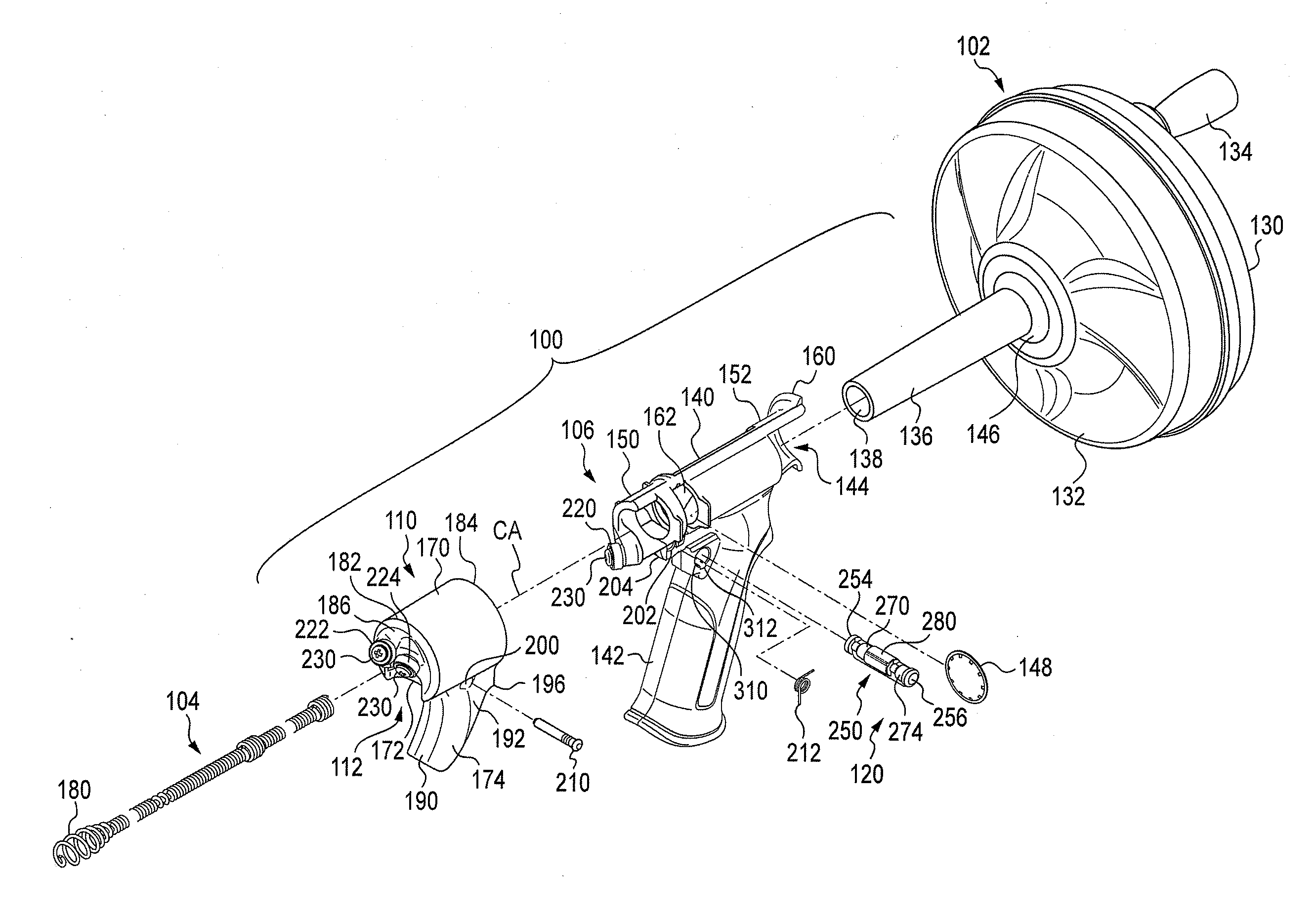
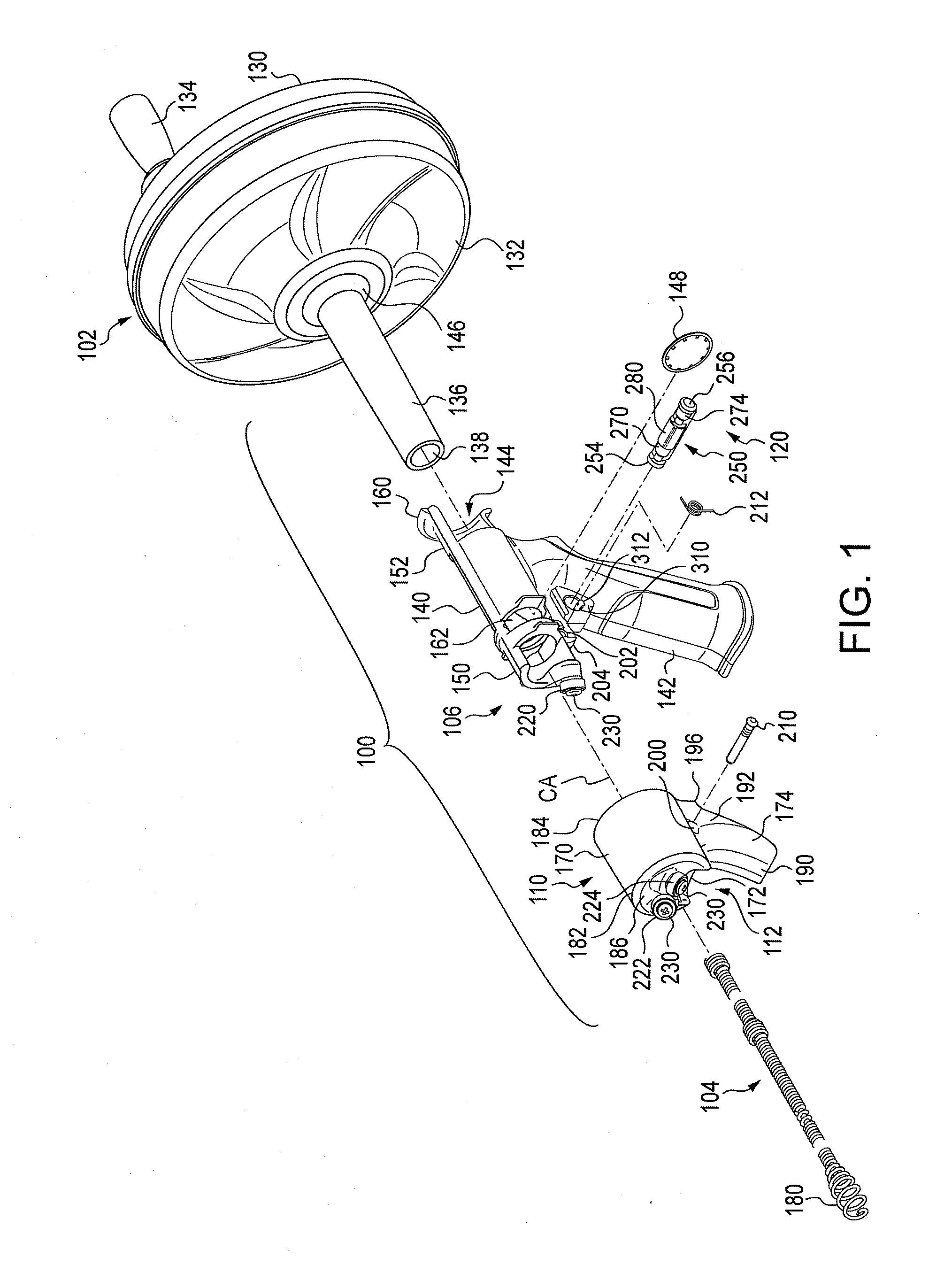
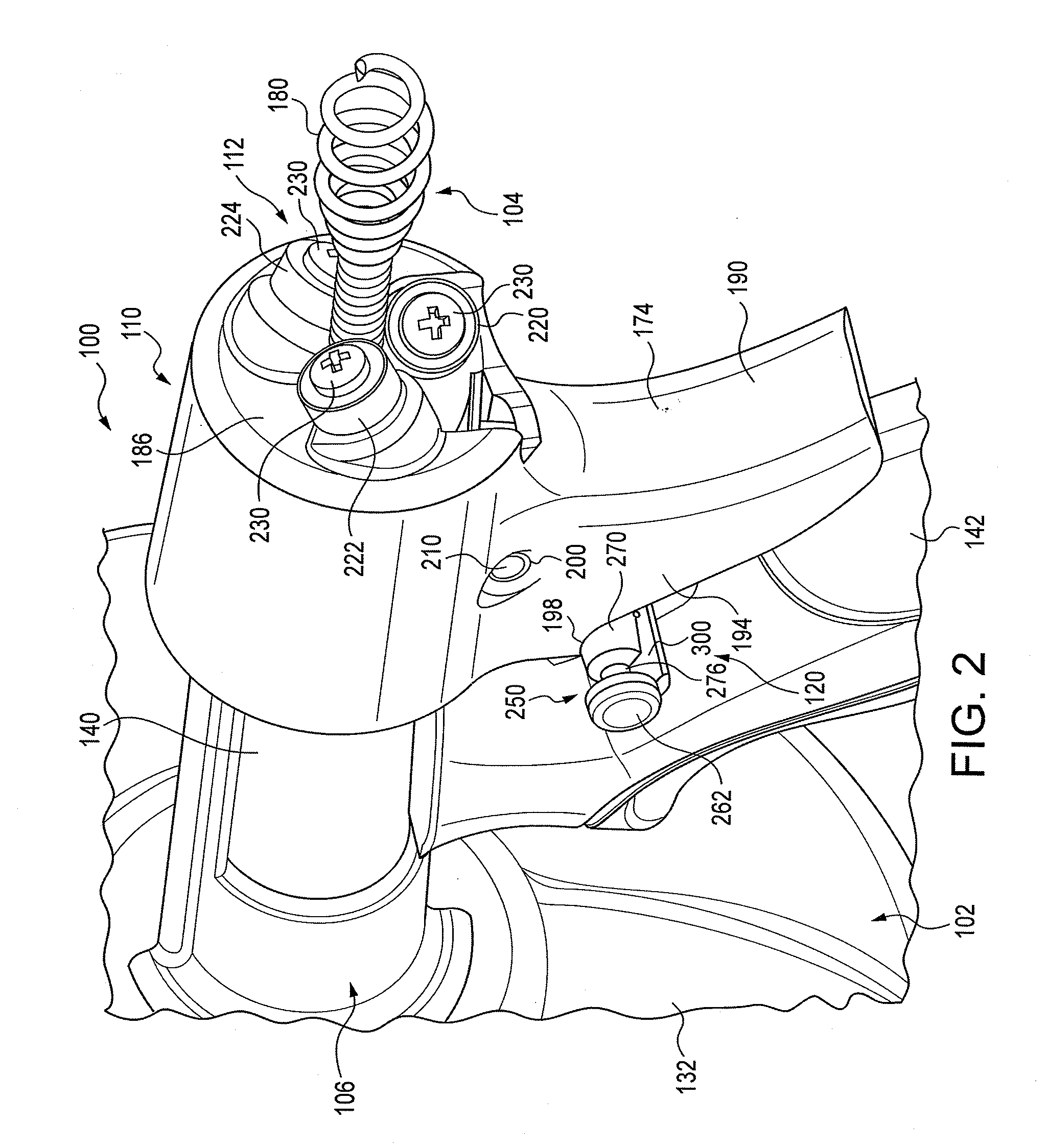
[0039]It should, of course, be understood that the description and drawings herein are merely illustrative and that various modifications and changes can be made in the structures disclosed without departing from the present disclosure. In general, the figures of the exemplary manual or hand operated drain cleaner are not to scale. It should be appreciated that the various identified components of the exemplary manual or hand operated drain cleaner disclosed herein are merely terms of art that may vary from one manufacturer to another and should not be deemed to limit the present disclosure.

[0040]Referring now to the drawings, wherein like numerals refer to like parts throughout the several views, FIGS. 1-4 illustrate a manual or hand operated drain cleaner or auger 100 in accordance with the present invention for cleaning a drain or sewer line. The drain cleaner 100 comprises a manually operated rotatable drum 102 for holding an elongated flexible cable or snake 104. A portion of t...


PUM


Abstract

A hand operated drain cleaner includes a manually operated rotatable drum and an elongated flexible cable at least partially held in the drum. A portion of the cable extending from the drum has a cable axis, and rotation of the drum rotates the cable portion about the cable axis. A handle is adapted to rotatably support the drum. The handle includes a barrel portion and a handle portion. A feed control device includes a housing having a feed passage axially therethrough for receiving the cable and a trigger for moving the feed control device between a non-actuating position and an actuating position. In the actuating position, a feed control device is pivoted relative to the handle such that the driving mechanism engages the cable thereby inducing axial movement of the cable via rotation of the drum. A locking mechanism is opera operably associated with the feed control device.

Description

CROSS REFERENCES TO RELATED APPLICATIONS[0001]This application claims priority upon U.S. provisional patent application Ser. No. 61 / 578,270 filed Dec. 21, 2011.BACKGROUND[0002]Exemplary embodiments herein generally relate to a drain cleaner or auger, and, more particularly, relate to a feed control device for a manual or hand operated drain cleaner or auger.[0003]Relatively small, portable drain cleaners are well known and, generally include a drain cleaning snake or cable coiled in a housing or drum from which an end of the cable extends for introduction into a drain or sewer line to be cleaned. For hand held and hand operated drain cleaners, a crank is attached to the drum to allow a user to rotate the drum about a support assembly from which a handle depends. The cable extends forwardly of the drum and is extended relative thereto for insertion into the drain to be cleaned and rotates with the drum so as to clear a blockage encountered in the drain. A user withdraws a length of t...

Claims


Application Information

Patent Timeline
Patent Type & Authority Applications(United States)
IPC IPC(8): B08B9/043G05G5/00
CPCB08B9/0436G05G5/005Y10T74/20636B08B9/045E03F9/005G05G5/00
Inventor RUTKOWSKI, MICHAEL J.GRESS, PAUL W.DUNKIN, JON R.
Owner EMERSON ELECTRIC CO
Why Eureka
Try Eureka