Automatic Rear Leg Control for Cold Planers

Active Publication Date: 2013-06-27
CATERPILLAR PAVING PROD INC
View PDF5 Cites 21 Cited by
  • Summary
  • Abstract
  • Description
  • Claims
  • Application Information

AI Technical Summary

Benefits of technology

[0005]In accordance with one aspect of the disclosure, a method of maintaining a machine substantially level with a first surface is disclosed for a machine including a front leg disposed on the first surface and a rear leg, a frame supported by the front leg and the rear leg, and a tool mounted on the frame between the front and rear legs. The method may comprise determining

Problems solved by technology

While Berning et al. discusses controlling the parallelism of the machine after a change in milling depth, i

Method used


Image

  • Automatic Rear Leg Control for Cold Planers
  • Automatic Rear Leg Control for Cold Planers
  • Automatic Rear Leg Control for Cold Planers

Examples


Embodiment Construction

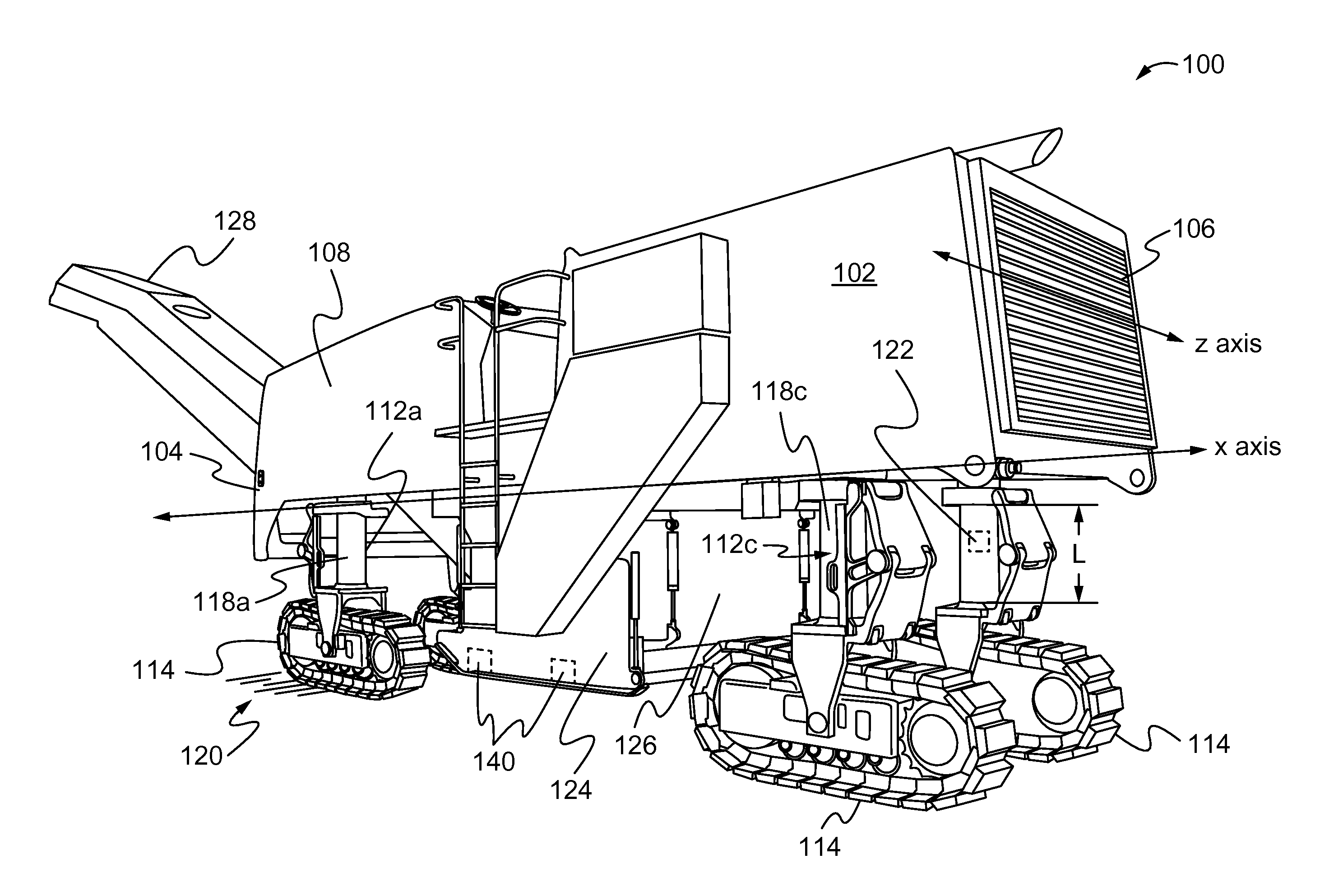
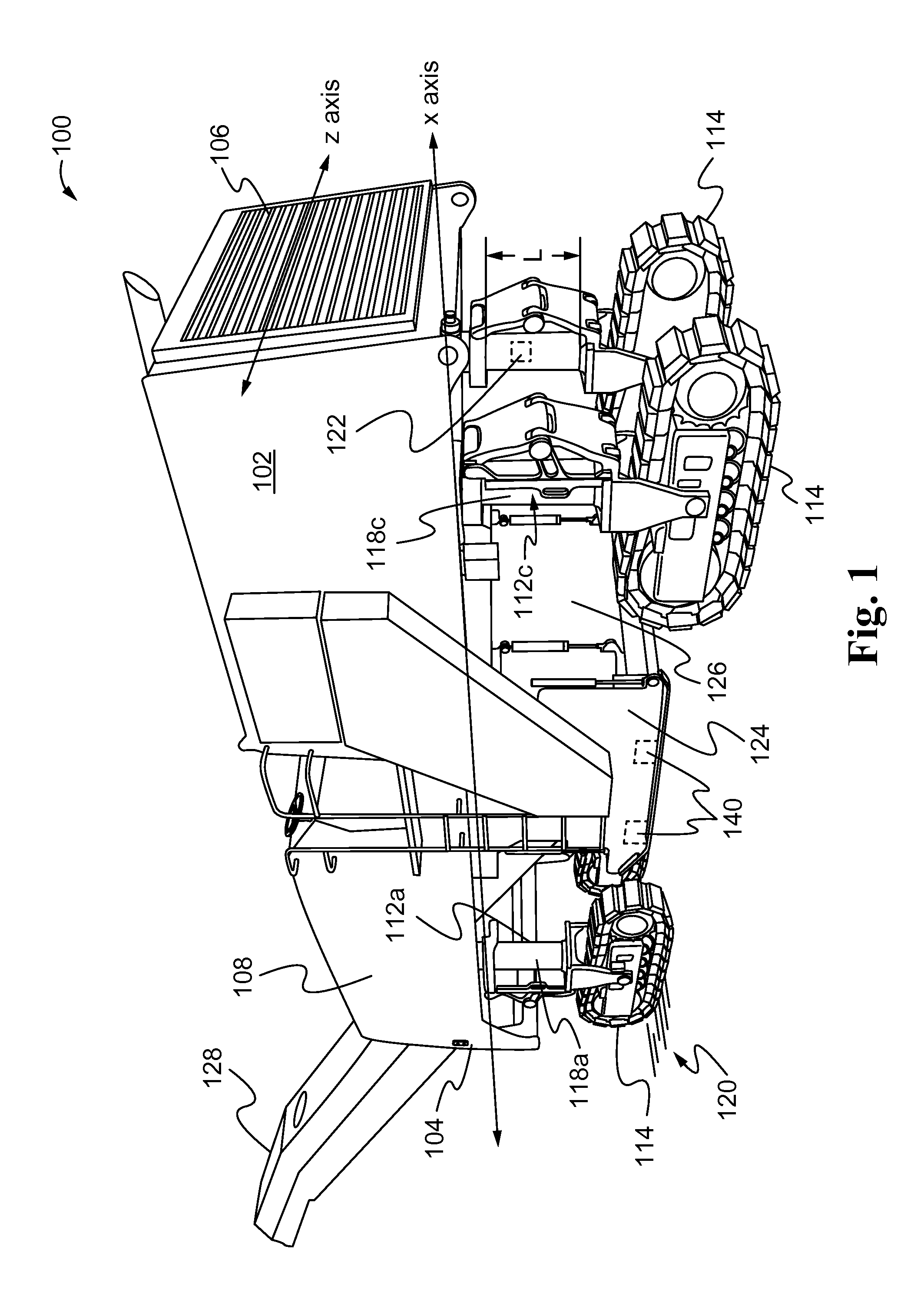
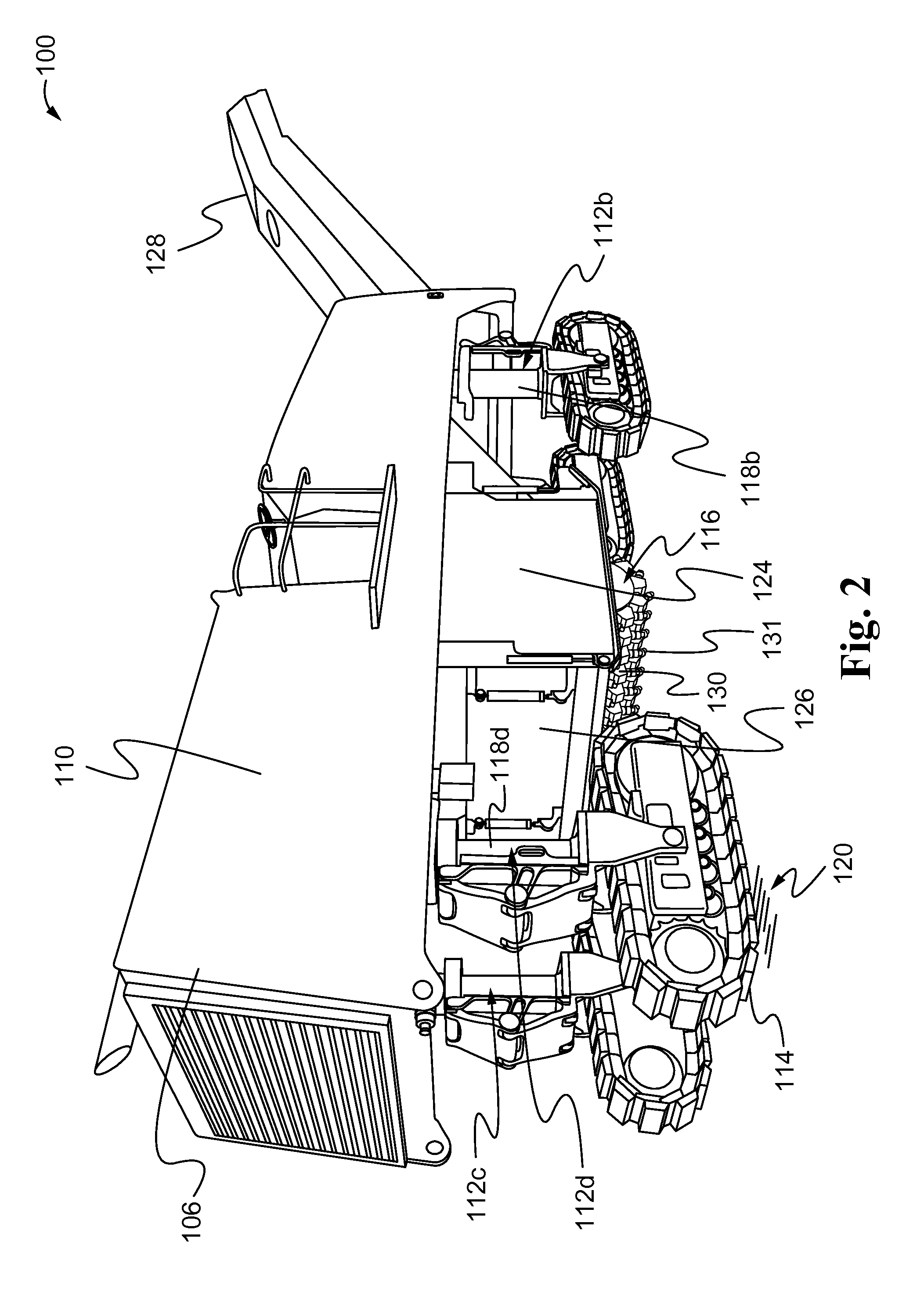
[0017]Machines may be configured to perform work operations at job sites. Examples of machines may include cold planers, on and off highway vehicles, construction equipment, and earth-moving equipment. While the teachings of this disclosure are not limited to a particular type of machine, an exemplary machine 100, a cold planer, is shown in FIGS. 1-3 and discussed below to illustrate the teachings of this disclosure.

[0018]The exemplary machine 100, a cold planer, may be configured to scarify, remove, mix, or reclaim material from the surface of bituminous, concrete, or asphalt roadways and other surfaces. Elements of the cold planer 100 may include a frame 102, support apparatus 112, a plurality of ground engaging units 114 and a tool 116. The frame 102 may include a front end 104, a rear end 106, a first side 108 and a second side 110. In an embodiment, there may be a plurality of support apparatus 112. Some of the plurality of support apparatus (referred to herein as the “front su...


PUM


Abstract

A method of maintaining a machine substantially level with a first surface is disclosed. The method may comprise determining an electronic travel path between a first point and a second point on a second surface, the second surface created by a tool removing a section of the first surface, and adjusting the length of the rear leg to maintain the frame substantially level to the first surface as the rear leg moves along the travel path from the first point to the second point in a forward direction. A machine for planing a road is disclosed that maintains a parallel orientation with the road during operation.

Description

TECHNICAL FIELD[0001]The present disclosure generally relates to machines for the treatment of roadway surfaces, and more particularly to a road planer for roadway surfacing operations.BACKGROUND[0002]Road milling machines, also known as cold planers, may be configured to scarify, remove, mix, or reclaim material from the surface of bituminous, concrete, or asphalt roadways and other surfaces using a rotatable planing tool mounted on a frame. The frame may be mounted on a plurality of tracks or wheels which support and transport the machine along the roadway surface.[0003]Typically, cold planers may also include a plurality of lifting members positioned near the front and rear of the frame. The lifting members may be adjusted between extending and retracted positions to control the depth and shape of a cut by raising or lowering the frame and rotatable planning tool.[0004]U.S. Publication No. 2009 / 0108663 (“Berning et al.”) published Apr. 30, 2009 is an example of prior art related ...

Claims


Application Information

Patent Timeline
IPC IPC(8): E01C23/12
CPCE01C23/088
Inventor KILLION, DANIEL H.
Owner CATERPILLAR PAVING PROD INC
Why Eureka
Try Eureka