Brushless motor drive device
a brushless dc motor and drive device technology, applied in the direction of motor/generator/converter stopper, electronic commutator, dynamo-electric converter control, etc., can solve the problem of thermal shutdown mechanism, and achieve the effect of preventing the frequency of pulse signal
- Summary
- Abstract
- Description
- Claims
- Application Information
AI Technical Summary
Benefits of technology
Problems solved by technology
Method used
Image
Examples
first embodiment
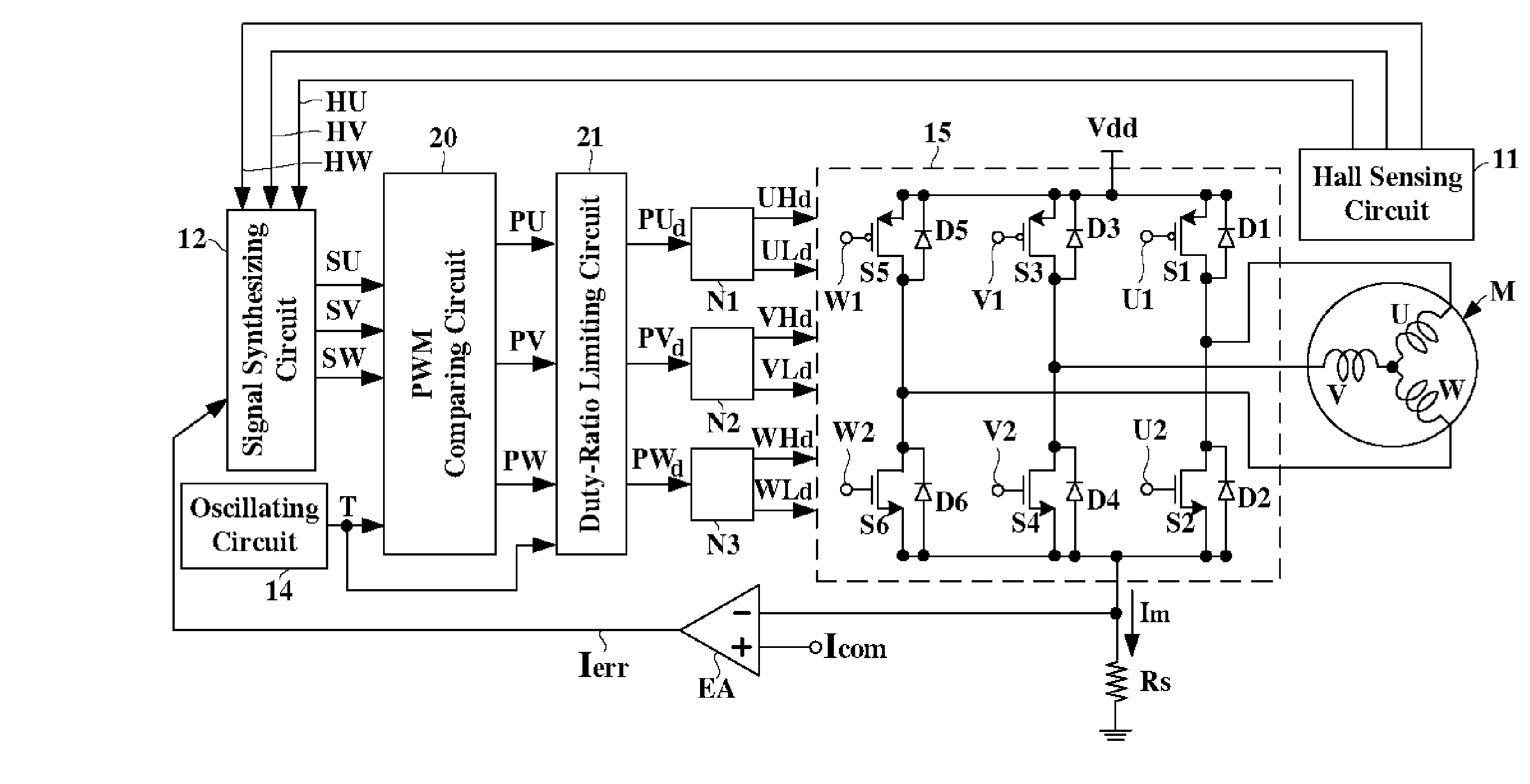
[0041]Therefore, the portion of the pulse signal PU-1d corresponding to the positive half of the drive signal SU has the duty ratio limited by the positive-half duty-ratio limit signal PH while the portion of the pulse signal PU-1d corresponding to the negative half of the drive signal SU has the duty ratio effectively limited by the negative-half duty-ratio limit signal PL. According to the present invention, a reliable rotation of the motor M is effectively achieved even when the difference between the motor drive current Im and the current command signal Icom becomes too large.
[0042]FIG. 4(a) is a detailed circuit diagram showing a second embodiment of a PWM comparing circuit 20-2 and a duty-ratio limiting circuit 21-2 according to the present invention. FIG. 4(b) is a waveform timing chart showing an operation of a second embodiment of a PWM comparing circuit 20-2 and a duty-ratio limiting circuit 21-2 according to the present invention. For the sake of simplicity, only is illus...
second embodiment
[0045]Therefore, the portion of the pulse signal PU-2d corresponding to the positive half of the drive signal SU has the duty ratio limited by the positive-half duty-ratio limit signal PH while the portion of the pulse signal PU-2d corresponding to the negative half of the drive signal SU has the duty ratio effectively limited by the negative-half duty-ratio limit signal PL. According to the present invention, a reliable rotation of the motor M is effectively achieved even when the difference between the motor drive current Im and the current command signal Icom becomes too large.
[0046]FIG. 5(a) is a detailed circuit diagram showing a third embodiment of a PWM comparing circuit 20-3 and a duty-ratio limiting circuit 21-3 according to the present invention. FIG. 5(b) is a waveform timing chart showing an operation of a third embodiment of a PWM comparing circuit 20-3 and a duty-ratio limiting circuit 21-3 according to the present invention. For the sake of simplicity, only is illustr...
third embodiment
[0049]Therefore, the portion of the pulse signal PU-3d corresponding to the positive half of the drive signal SU has the duty ratio limited by the positive-half duty-ratio limit signal PH while the portion of the pulse signal PU-3d corresponding to the negative half of the drive signal SU has the duty ratio effectively limited by the negative-half duty-ratio limit signal PL. According to the present invention, a reliable rotation of the motor M is effectively achieved even when the difference between the motor drive current Im and the current command signal Icom becomes too large.
[0050]FIG. 6(a) is a detailed circuit diagram showing a fourth embodiment of a PWM comparing circuit 20-4 and a duty-ratio limiting circuit 21-4 according to the present invention. FIG. 6(b) is a waveform timing chart showing an operation of a fourth embodiment of a PWM comparing circuit 20-4 and a duty-ratio limiting circuit 21-4 according to the present invention. For the sake of simplicity, only is illus...
PUM
 Abstract
Description
Claims
Application Information
 - R&D
- Intellectual Property
- Life Sciences
- Materials
- Tech Scout
- Unparalleled Data Quality
- Higher Quality Content
- 60% Fewer Hallucinations
Browse by: Latest US Patents, China's latest patents, Technical Efficacy Thesaurus, Application Domain, Technology Topic, Popular Technical Reports.
© 2025 PatSnap. All rights reserved.Legal|Privacy policy|Modern Slavery Act Transparency Statement|Sitemap|About US| Contact US: help@patsnap.com


