
Hydrogen generating apparatus and fuel cell power generation system controlling amount of hydrogen generation

a technology of hydrogen generation and generating apparatus, which is applied in the direction of electrochemical generators, instruments, electric circuits machined, etc., can solve the problems of high reforming temperature, complex system, and high consumption of driving power, and achieve the effect of reducing and increasing the duty ratio of the switch control signal

Inactive Publication Date: 2013-10-08
SAMSUNG ELECTRO MECHANICS CO LTD
View PDF24 Cites 0 Cited by
  • Summary
  • Abstract
  • Description
  • Claims
  • Application Information

AI Technical Summary

Benefits of technology

The present invention provides a hydrogen generating apparatus, a fuel cell power generation system, a method of controlling the quantity of hydrogen generation, and a recorded medium recorded with a program performing the method that can prevent waste or risk of leaking surplus hydrogen in the air simply by turning on the switch and reduce the noise and power consumption by not using a gas pump or a liquid pump. The method of controlling an amount of hydrogen generation in accordance with another embodiment of the present invention, which measures the present voltage of the rechargeable battery, compares the present voltage with a fully-charged voltage, and increasing the duty ratio of switch control signal if the present voltage is smaller than the fully-charged voltage, and minimizing the duty ratio of switch control signal if the present voltage is equal to or greater than the fully-charged voltage, in which the switch control signal controls the on / off status of the switch within one cycle in accordance with the duty ratio.

Problems solved by technology

However, the former case requires a high reforming temperature, has a complicated system, consumes driving power, and contains impurities (e.g., CO2 and CO) in addition to pure hydrogen.
The latter case deteriorates power density due to a low rate of a chemical reaction in the anode and a cross-over of hydrocarbon through the membrane.

Method used


Image

  • Hydrogen generating apparatus and fuel cell power generation system controlling amount of hydrogen generation
  • Hydrogen generating apparatus and fuel cell power generation system controlling amount of hydrogen generation
  • Hydrogen generating apparatus and fuel cell power generation system controlling amount of hydrogen generation

Examples


Embodiment Construction

[0058]Since there can be a variety of permutations and embodiments of the present invention, certain embodiments will be illustrated and described with reference to the accompanying drawings. This, however, is by no means to restrict the present invention to certain embodiments, and shall be construed as including all permutations, equivalents and substitutes covered by the spirit and scope of the present invention. Throughout the drawings, similar elements are given similar reference numerals. Throughout the description of the present invention, when describing a certain technology is determined to evade the point of the present invention, the pertinent detailed description will be omitted.

[0059]Terms such as “first” and “second” can be used in describing various elements, but the above elements shall not be restricted to the above terms. The above terms are used only to distinguish one element from the other. For instance, the first element can be named the second element, and vic...


PUM

PropertyMeasurementUnit
voltageaaaaaaaaaa
electric currentaaaaaaaaaa
temperatureaaaaaaaaaa

Abstract

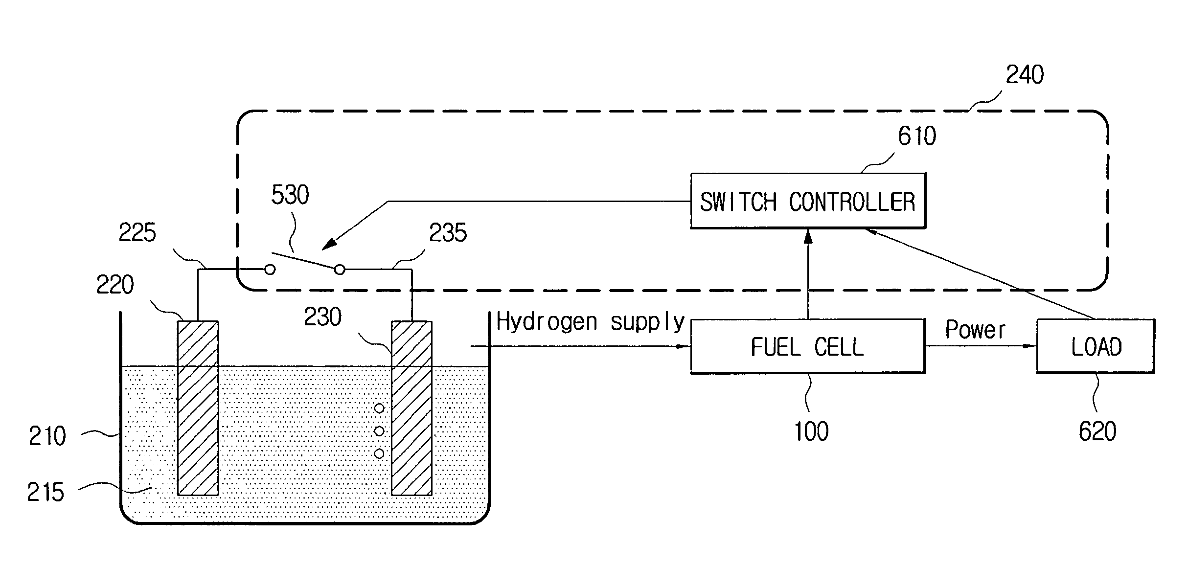
Hydrogen generating apparatus that is capable of controlling the amount of hydrogen generation. The hydrogen generating apparatus has an electrolyzer, a first electrode, a second electrode, a switch, which is located between the first electrode and the second electrode, a flow rate meter, which measures an amount of hydrogen generation in the second electrode, and a switch controller, which receives a set value, compares the amount of hydrogen generation measured by the flow rate meter with the set value, and controls an on / off status of the switch. The amount of hydrogen generation can be controlled by use of on / off time and / or on / of frequency of the switch.

Description

CROSS-REFERENCE TO RELATED APPLICATIONS[0001]This application is a continuation-in-part of U.S. patent application Ser. No. 11 / 812,656, filed on Jun. 20, 2007 now U.S. Pat. No. 7,879,205. And this application claims the benefit of Korean Patent Application No. 10-2007-0017343 filed with the Korean Intellectual Property Office on Feb. 21, 2007, the disclosure of which is incorporated herein by reference in its entirety.BACKGROUND OF THE INVENTION[0002]1. Field of the Invention[0003]The present invention relates to a hydrogen generating apparatus, more particularly to a hydrogen generating apparatus that can control the amount of generation of hydrogen supplied to a fuel cell.[0004]2. Background Art[0005]A fuel cell refers to an energy conversion apparatus that directly converts chemical energy of a fuel (hydrogen, LNG, LPG, methanol, etc.) and air to electricity and / or heat by means of an electrochemical reaction. Unlike a conventional power generation technology that requires fuel c...

Claims


Application Information

Patent Timeline
Patent Type & Authority Patents(United States)
IPC IPC(8): B23H3/02H01M8/06
CPCH01M8/0656H01M8/186H01M16/006Y02E60/528Y02E60/10Y02E60/50
Inventor GIL, JAE-HYOUNGJANG, JAE-HYUKKUNDU, ARUNABHAKIMCHAE, KYOUNGSOO
Owner SAMSUNG ELECTRO MECHANICS CO LTD
Learn More