
Mcu integration battery charger/discharger

Inactive Publication Date: 2013-07-04
SAMYA TECHNOLOGY CO LTD
View PDF11 Cites 19 Cited by
  • Summary
  • Abstract
  • Description
  • Claims
  • Application Information

AI Technical Summary

Benefits of technology

[0031]According to the forgoing techniques, the present invention is provided and integrated with the MCU and the charging/discharging switch set for constituting a circuit structure featuring an “separate detection charging and series-connected and combined discharging mode” with

Problems solved by technology

A disposable battery (or a primary battery) is discarded after use, not only increasing the cost, but also causing environmental pollutions.
1. The lithium battery usually comes with a different specification for each of the electronic products. Even for the electronic products of the same brand, such as the Nokia mobile phones, there are tens of models of the lithium batteries, and thus causing tremendous inconvenience and trouble to users.
2. The lithium battery contains an electrolytic unit, and there is a safety concern such as possible explosion occurred when a current is passed.
3. Most of the present portable powers use a built-in lithium battery as an energy storage unit, but it generally does not come with a standard size for general electronic consumer products. As a result, the fully charged battery cannot be used alone when it is removed. Even though it can be removed, there are so many specifications of the lithium batteries, and such application is impractical.
1. As shown in FIG. 1, which illustrates a charging circuit of a conventional parallel charger, the batteries B1˜B4 connected in parallel are charged by the charging circuit. The advantage lies in that each of the batteries obtains a roughly the same charging voltage. The user can be free of the problem with batteries that are overcharged or undercharged. However, the disadvantage of the parallel charging mode is that the batteries can't be rapidly charged. Each of the batteries h

Method used


Image

  • Mcu integration battery charger/discharger
  • Mcu integration battery charger/discharger
  • Mcu integration battery charger/discharger

Examples


Embodiment Construction

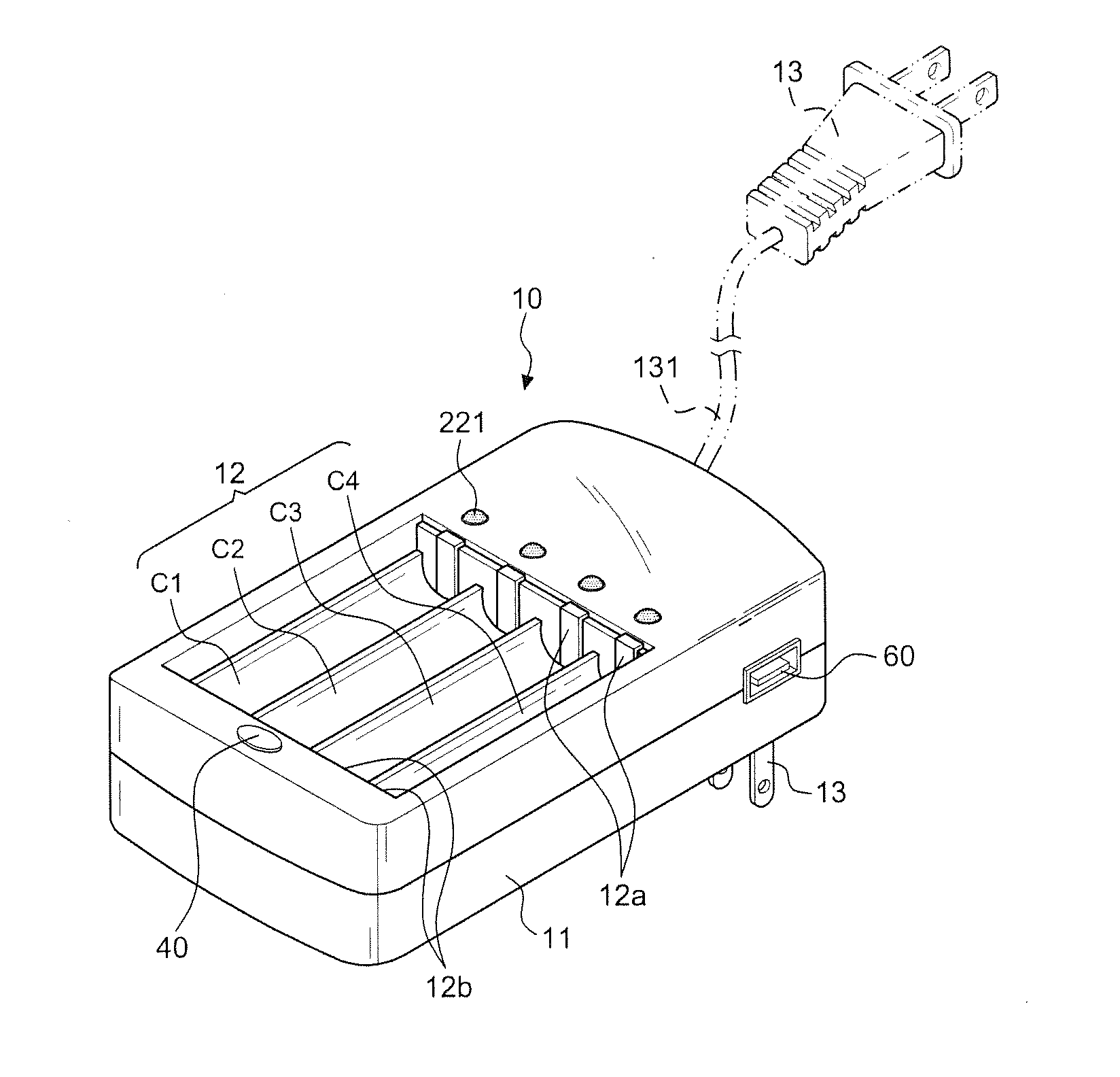
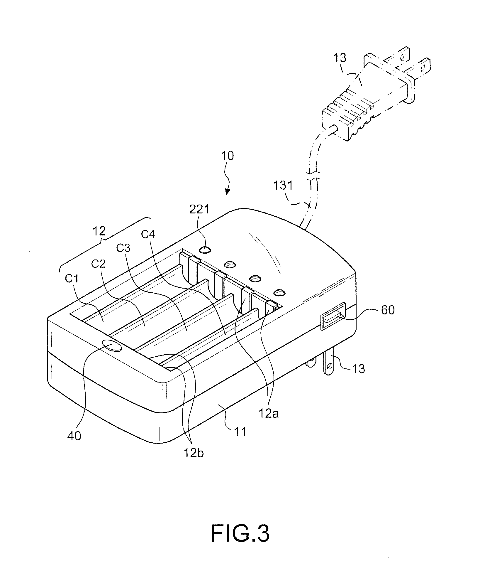
[0051]With reference to FIG. 3 for a perspective view of a battery charger 10 of the present invention, the charger 10 comprises: a casing 11, for containing and covering charging components (such as a switching power supply and a charging circuit), and a charging base 12 disposed on a surface of the casing 11 and having a plurality of charging compartments provided for placing a plurality of AA or AAA batteries B1˜B4 therein. In this preferred embodiment, there are four charging compartments C1, C2, C3, C4, but the invention is not limited to such quantity only. In a small charger, there are two charging compartments. Four charging compartments are used as an example for the description of a preferred embodiment and the illustration of its related drawings as follows. The casing 11 further comprises a plug 13 connectible to an external power source 80, wherein the plug 13 of this preferred embodiment is foldable and disposed at the bottom of the casing 11. Of course, an external po...


PUM


Abstract

An MCU integration battery charger/discharger, and more particularly a series circuit for detecting the battery charging process and for conducting a series combined discharging process on the same battery charger. The present invention provides an MCU and a charging/discharging switch set to switch to the “separate detection charging or series-connected and combined discharging mode,” and a discharging button enables the stored electric energy be released for use by the series-connected separate detection charging circuits. Moreover, the charger can deliver DC power via tan output port to the 3C electronic products for the charging purpose. Meanwhile, the problems of conventional AA or AAA battery chargers and lithium batteries designed as a portable power are overcome, thereby enhancing the effect and safety of the charger.

Description

BACKGROUND OF THE INVENTION[0001](a) Field of the Invention[0002]The present invention relates to an MCU integration battery charger / discharger, and more particularly to a charger designed for charging, discharging and supplying electric power to an AA or AAA rechargeable battery, and an MCU and a charging / discharging switch set are provided to integrate a circuit structure with “a separate detection charging circuit and a series-connected and combined discharging circuit.”[0003](b) Description of the Related Art[0004]As portable 3C electronic products become increasingly more popular, the demand for batteries becomes increasingly higher as well. A disposable battery (or a primary battery) is discarded after use, not only increasing the cost, but also causing environmental pollutions. Therefore, a rechargeable battery (or a secondary battery) has a higher consumption than that of the primary battery since the rechargeable battery can save costs and reduce contaminations of waste bat...

Claims


Application Information

Patent Timeline
IPC IPC(8): H02J7/00
CPCH02J7/00H02J7/0016H02J7/0019H02J2207/20H02J7/0025
Inventor YANG, FU-I
Owner SAMYA TECHNOLOGY CO LTD
Learn More