
Illuminator arrangement with less heat intervention

Active Publication Date: 2013-07-04
LEE WEN SUNG
View PDF4 Cites 28 Cited by
  • Summary
  • Abstract
  • Description
  • Claims
  • Application Information

AI Technical Summary

Benefits of technology

The present invention is an improved engine illuminator arrangement. It has a reflecting body with a top opening and a bottom opening, a lens, a cone surface, and at least one slot. A heat pipe is extended from the aluminum base and connected to the slot. A light source is assembled on the top of the aluminum base and movable in the receiving space. The heat pipe is made of a good heat conductor. The bottom opening is smaller than the size of the aluminum base, and the amount of heat pipe is the same as the amount of slots. The heat pipe is bent with an adaptive distance from the aluminum base. This arrangement allows the aluminum base to move up and down relative to the top opening, and the heat pipe to move up and down along the slot with the motion of the aluminum base. This results in the light source moving toward or away from the lens, diffusing or focusing the light. This invention has improved heat dissipation and lighting control.

Problems solved by technology

Light emitting efficiency of the LED illuminator is easily influenced by heat, especially under high power of the electric current for a long time, and the result is the unstable color performance and the higher color temperature.
First, a heat-dissipating area of the aluminum base is not large enough to well dissipate the heat from the light source because the size of the aluminum base is limited to be smaller than the size of the bottom opening.
Second, if a manufacture enlarges the size of the aluminum base, an interaction between the aluminum base and the reflecting body limits the moving space of the light source so that the performances of the focusing light and diffusing light are degraded.

Method used


Image

  • Illuminator arrangement with less heat intervention
  • Illuminator arrangement with less heat intervention
  • Illuminator arrangement with less heat intervention

Examples


Embodiment Construction

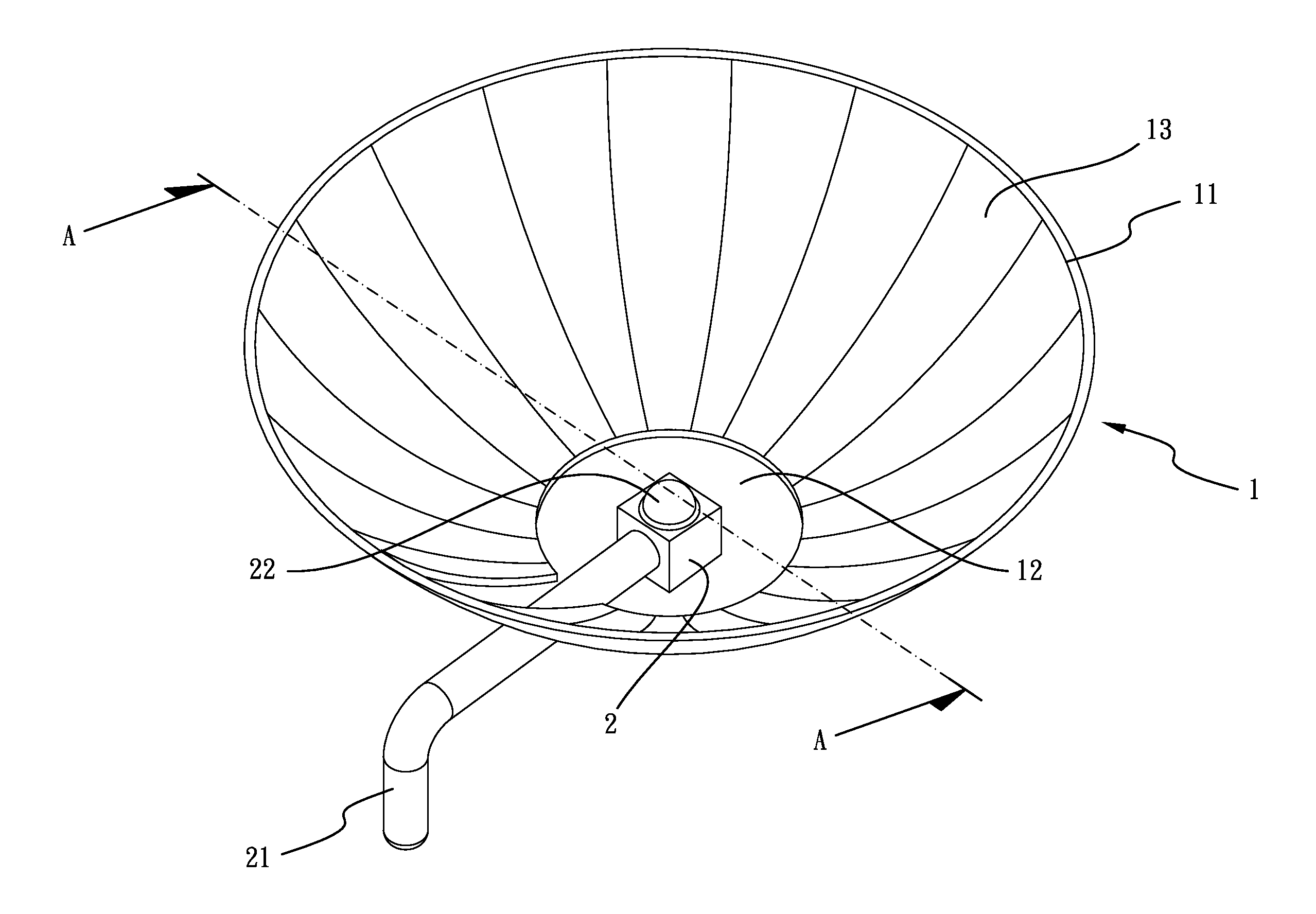
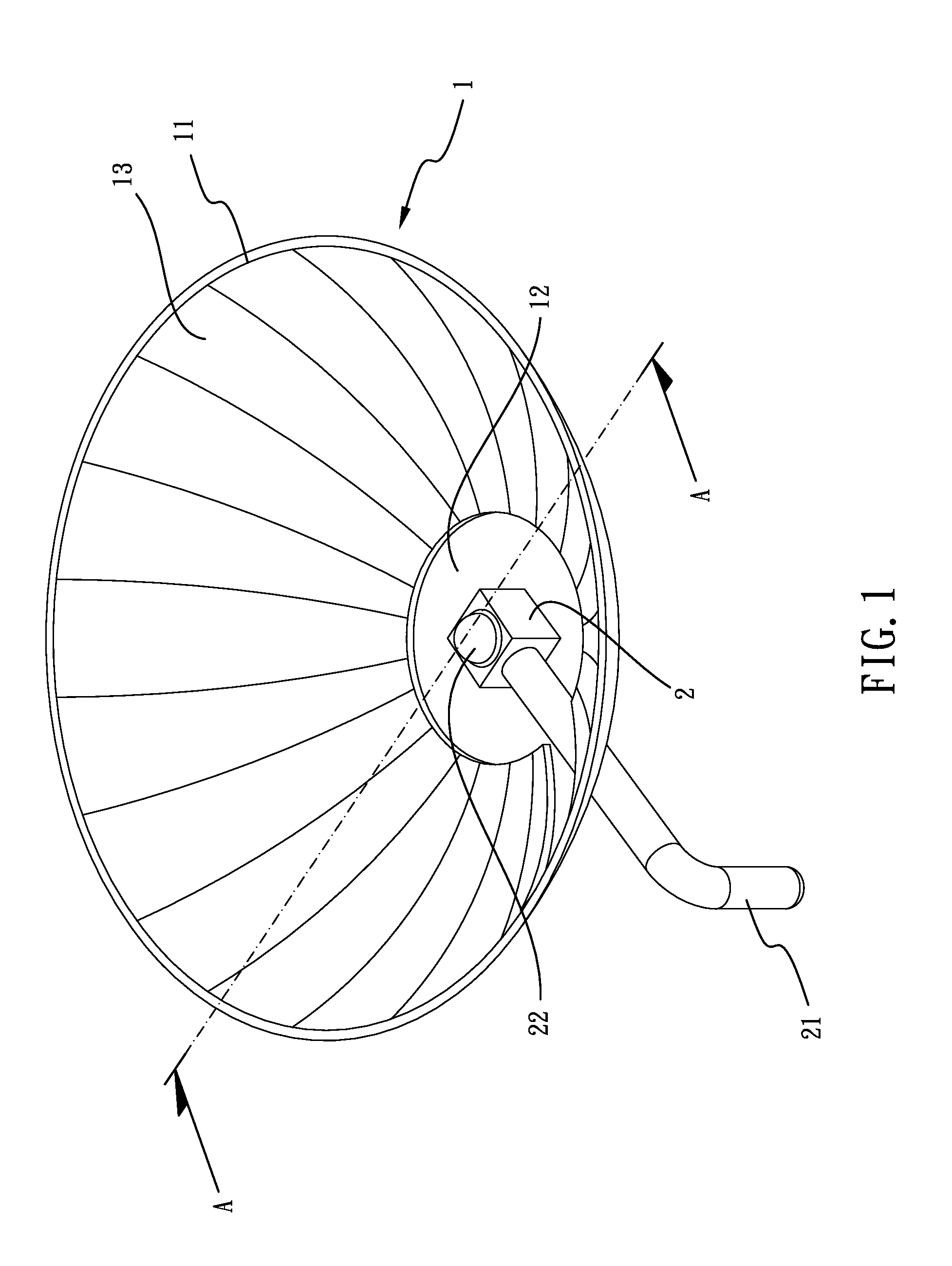
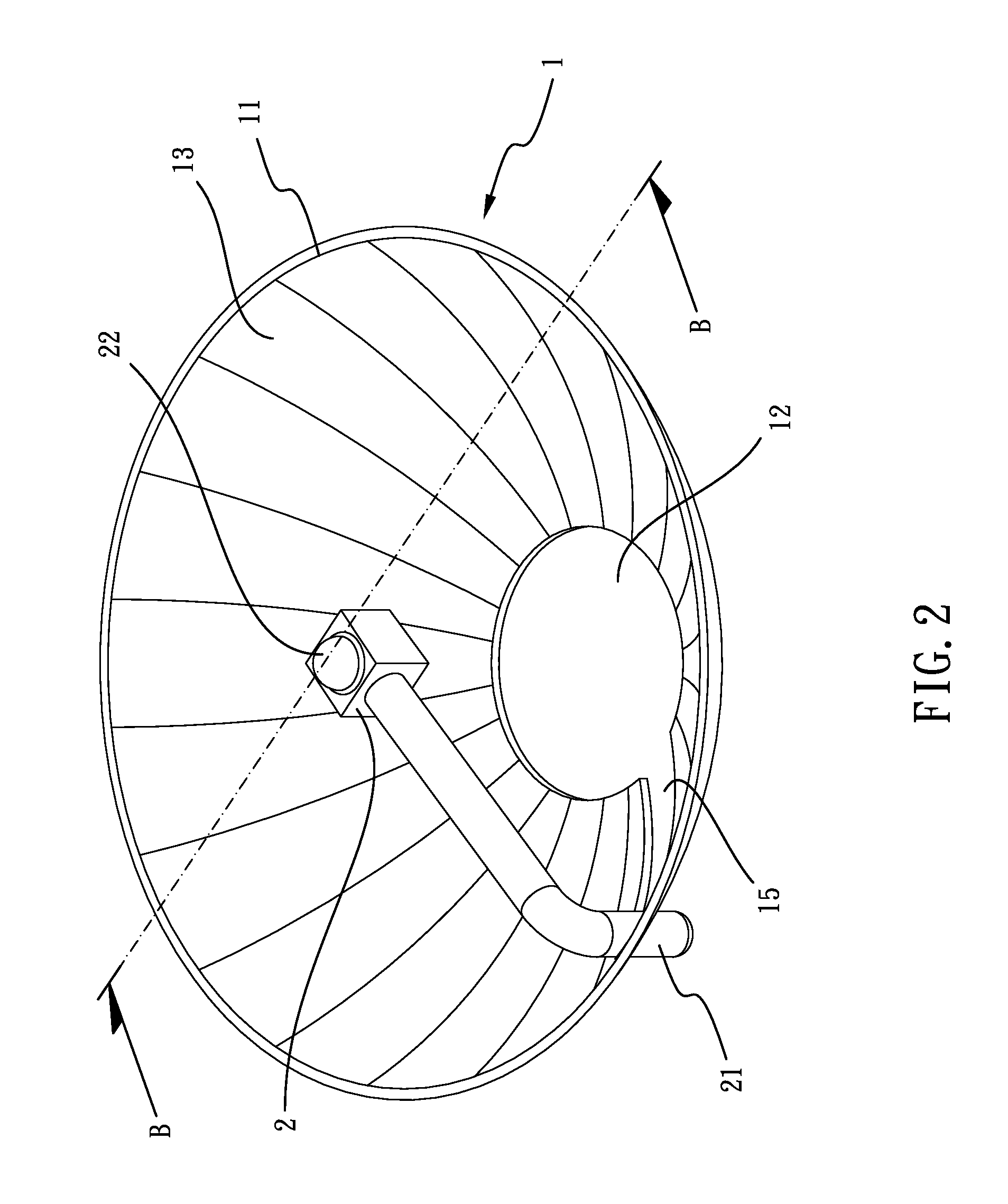
[0022]Referring to FIGS. 1-4, an illuminator arrangement with less heat intervention in accordance with the present invention comprises a reflecting body 1 and an aluminum base 2. The reflecting body 1 has a top opening 11 opened at one end thereof for transmitting the light freely. The reflecting body 1 has a bottom opening 12 opened at another end thereof. A cone surface 13 is formed between the top opening 11 and the bottom opening 12 at the reflecting body 1. A receiving space 14 is defined between the top opening 11, the bottom opening 12 and the cone surface 13. At least one slot 15 is opened along the cone surface 13. One end of the slot 15 is communicated with the bottom opening 12. A lens 3 is assembled above the top opening 11. The aluminum base 2 is assembled at the bottom opening 12. At least one heat pipe 21 is extended from the periphery of the aluminum base 2. The heat pipe 21 is corresponding to the slot 15. The amount of the heat pipe 21 is the same from the amount ...


PUM


Abstract

An illuminator arrangement with less heat intervention includes a reflecting body having a top opening and a bottom opening, a lens assembled above the top opening, an aluminum base assembled at the bottom opening, at least one heat pipe extended from the aluminum base, a light source assembled on the aluminum base, the heat pipe being made of the material which is a good heat conductor. Under this arrangement, the aluminum base could be moved up and down relative to the top opening so that the light source on the aluminum base could move toward the lens or moves away from the lens so as to diffuse light or focus light. Furthermore, the heat pipe dissipates the heat generated by the light source away from the reflecting body.

Description

BACKGROUND OF THE INVENTION[0001]1. Field of the Invention[0002]The present invention relates to an illuminator, and more particularly to an illuminator arrangement with less heat intervention.[0003]2. Description of Related Art[0004]A conventional illuminator includes a reflecting body and an aluminum base. The reflecting body has a top opening and a bottom opening. A cone surface is formed between the top opening and the bottom opening at the reflecting body. A lens is assembled above the top opening The aluminum base is located at the bottom opening. The aluminum base could be moved up and down relative to the bottom opening. The size of the aluminum base is smaller than the size of the bottom opening so that the aluminum base could pass through the bottom opening. A light source is located on the aluminum base and is corresponding to the lens so that the light source could move away from the lens or move toward the lens via the motion of the aluminum base. Under this arrangement...

Claims


Application Information

Patent Timeline
IPC IPC(8): F21V19/02
CPCF21V29/006F21V5/04F21Y2101/02F21V13/04F21V14/02F21V7/06F21Y2115/10F21V29/51
Inventor LEE, WEN-SUNG
Owner LEE WEN SUNG
Features
  • Generate Ideas
  • Intellectual Property
  • Life Sciences
  • Materials
  • Tech Scout
  • Unparalleled Data Quality
  • Higher Quality Content
  • 60% Fewer Hallucinations
Learn More