Supercharge Your Innovation With Domain-Expert AI Agents!

Floating fastener with expanded application flexibility

a floating fastener and flexible technology, applied in the direction of threaded fasteners, screwdrivers, manufacturing tools, etc., can solve the problems of affecting the operation of further re-installation, occupying much the inside space of complicated locking of multiple plate members in the computer or electronic product by screws and nuts, etc., to achieve the effect of expanding the flexibility of application

Inactive Publication Date: 2013-07-04
HANWIT PRECISION IND LTD
View PDF16 Cites 20 Cited by
  • Summary
  • Abstract
  • Description
  • Claims
  • Application Information

AI Technical Summary

Benefits of technology

The present invention is a floating fastener that allows for more flexibility in its use. The aim is to make it practical for fastening multiple plate members in a machine or electronic device. This means that the available space can be utilized better.

Problems solved by technology

When unlocking the plate members, the component parts of the fastening screw assemblies may fall from the plate members and missed accidentally, affecting further re-installation operation.
However, installation of multiple circuit boards in a computer or electronic product occupies much the inside space of the computer or electronic product.
In actual practice, using screws and nuts to lock plate members has the drawbacks as follows:1. It is complicated to lock multiple plate members in a computer or electronic product by screws and nuts.
Further, it requires much labor and time to unfasten the screws and nuts for removal of the plate members for maintenance or repair.2. Using screws and nuts to lock two plate members (circuit boards) in a computer or electronic product in a stack does not allow installation of an extra plate member (circuit board) to the stacked plate members (circuit boards) to expand the function.

Method used


Image

  • Floating fastener with expanded application flexibility
  • Floating fastener with expanded application flexibility
  • Floating fastener with expanded application flexibility

Examples


Embodiment Construction

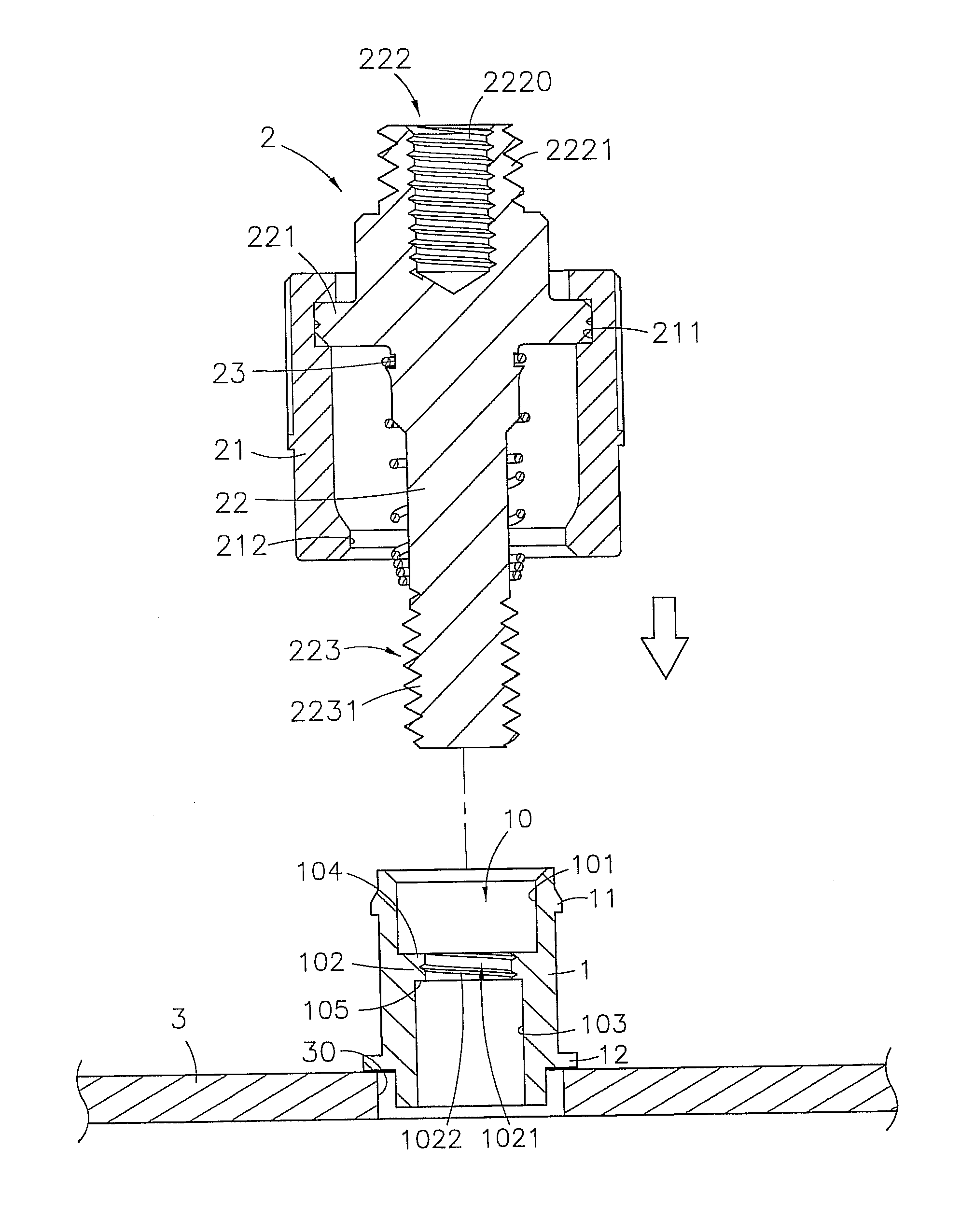
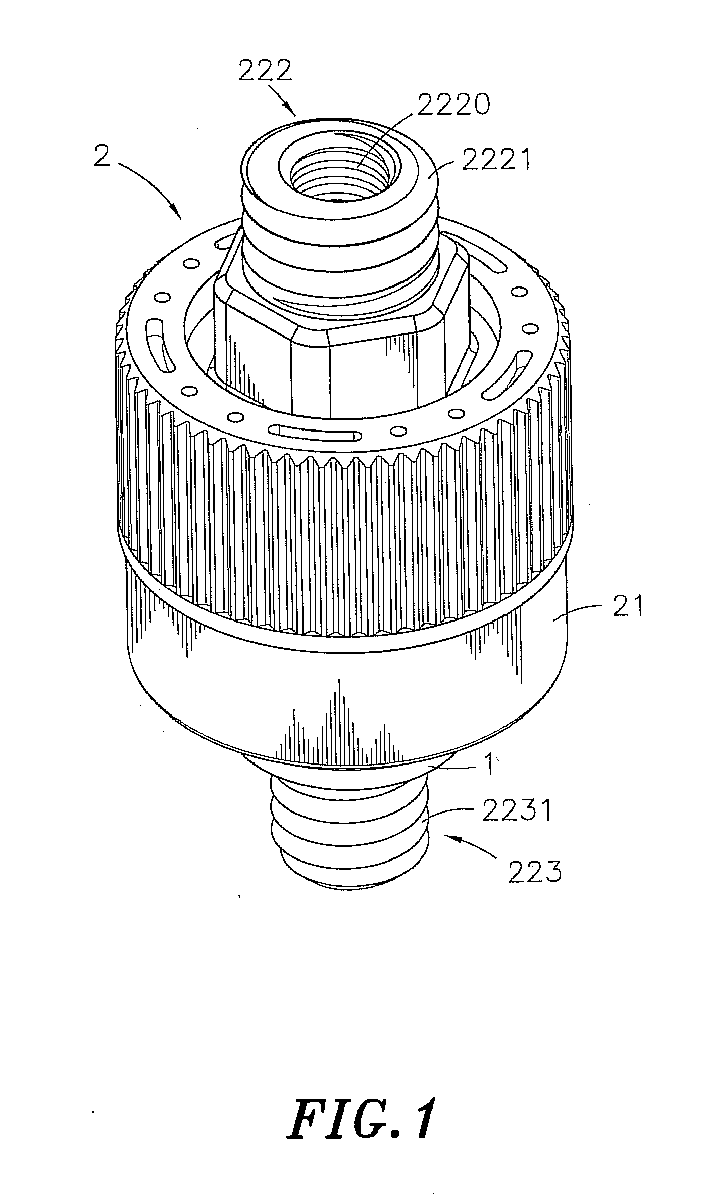
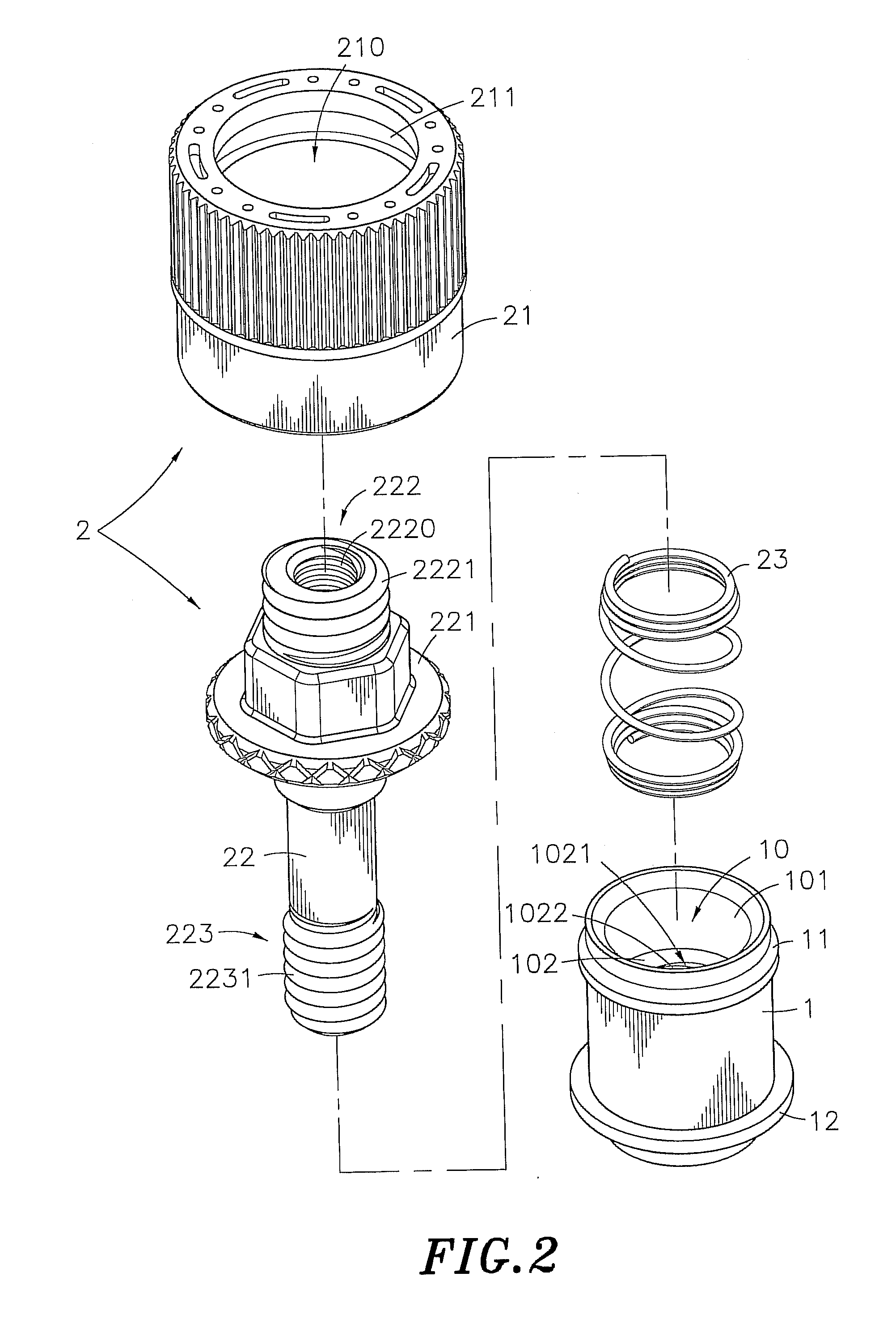
[0023]Referring to FIGS. 1, 2 and 3, a floating fastener with expanded application flexibility in accordance with a first embodiment of the present invention is shown. The floating fastener comprises a mounting base member 1 and a fastener 2.

[0024]The mounting base member 1 is a hollow cylinder defining therein an open space 10 that extends through opposing top and bottom ends thereof. The mounting base member 1 comprises a first accommodation chamber 101 formed of an upper part of the open space 10, a second accommodation chamber 103 formed of a lower part of the open space 10, a partition wall 102 transversely disposed in the open space 10 on the middle between the first accommodation chamber 101 and the second accommodation chamber 103, a through hole 1021 cut through the partition wall 102 in communication between the first accommodation chamber 101 and the second accommodation chamber 103, a first shoulder 104 formed of an upper part of the partition wall 102 and facing toward ...


PUM


Abstract

A floating fastener includes a mounting base member bonded to a first plate member, and a fastener, which includes a locking member inserted through the mounting base member and having a top connection end piece for fastening to a fastener at a third plate member to secure a third plate member to the first plate member in a stack, a bottom locking end piece for fastening to a second plate member to lock the second plate member to the first plate member in a stack, a knob affixed to a middle part of the locking member and slidably coupled to the mounting base member for operation by a user to fasten the locking member to the second plate member, and a spring member supporting the locking member in the mounting base member in a floating manner.

Description

BACKGROUND OF THE INVENTION[0001]1. Field of the Invention[0002]The present invention relates to fastener means for joining plate members and more particularly, to a floating fastener, which is practical for detachably fastening multiple plate members in a machine or electronic device in a stack, saving much machine or device space.[0003]2. Description of the Related Art[0004]When fastening plate members together, a fastening screw assembly formed of a knob, a mounting base member and a screw is usually used. During installation, the screw and the mounting base member are secured to the first plate member, and then the knob is rotated to drive the screw into the second plate member, and then a hand tool is used to fasten tight the screw, affixing the first and second plate members together. This design of fastening screw assembly can be used in a machine tool to join plate members together. In a machine tool where plate members are to be fastened together are commonly at the locatio...

Claims


Application Information

Patent Timeline
Patent Type & Authority Applications(United States)
IPC IPC(8): F16B1/00
CPCF16B5/0233Y10T403/477F16B35/06
Inventor TSENG, YING-CHIH
Owner HANWIT PRECISION IND LTD
Features
  • R&D
  • Intellectual Property
  • Life Sciences
  • Materials
  • Tech Scout
  • Unparalleled Data Quality
  • Higher Quality Content
  • 60% Fewer Hallucinations
Learn More