Display system and display method for video wall

a technology of display system and video wall, which is applied in the field of display system and display method, can solve the problems of limited length and less flexibility of conventional methods, and achieve the effect of lifting the length limitation of a signal transmission line and enhancing the flexibility of application of video walls

Active Publication Date: 2014-12-16
VIA TECH INC
View PDF7 Cites 20 Cited by
  • Summary
  • Abstract
  • Description
  • Claims
  • Application Information

AI Technical Summary

Benefits of technology

[0007]The invention provides a display system and a display method for video walls, so as to enhance application flexibilities of the video walls and to lift a length limitation of a signal transmission line.
[0010]According to the foregoing, the invention uses the network as a medium for transmitting the image between the server and the player devices, and as long as the network exists, the player devices and video wall may be set up. Hence, a distance between the server and the video wall is not restricted by the length limitation of signal transmission line, and may increase or decrease an amount of the server, the player device or the display depending on application requirements, thus achieving a great flexibility in application.

Problems solved by technology

The conventional methods are less flexible and are also limited by lengths of the signal transmission lines.

Method used


Image

  • Display system and display method for video wall
  • Display system and display method for video wall
  • Display system and display method for video wall

Examples


Embodiment Construction

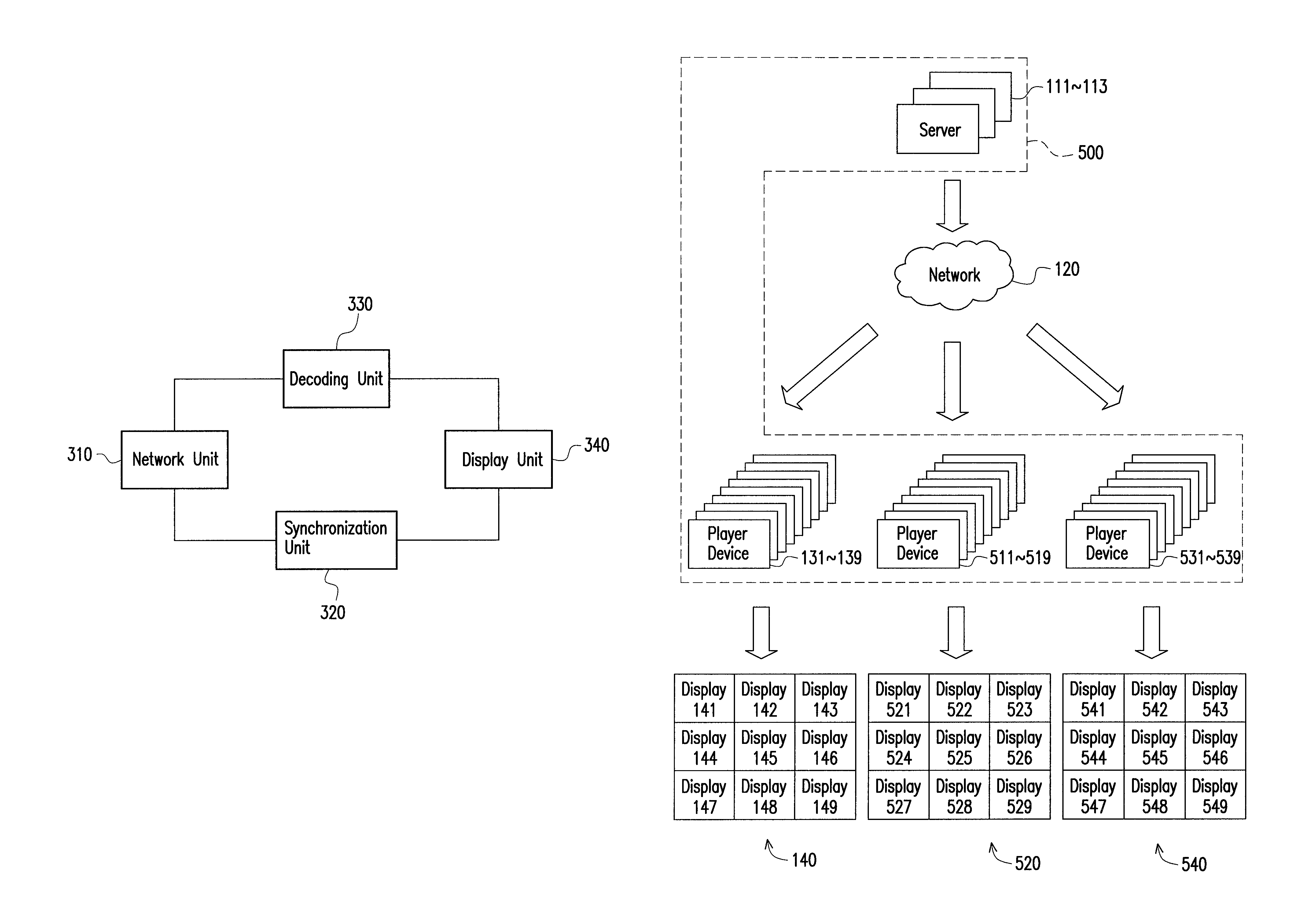
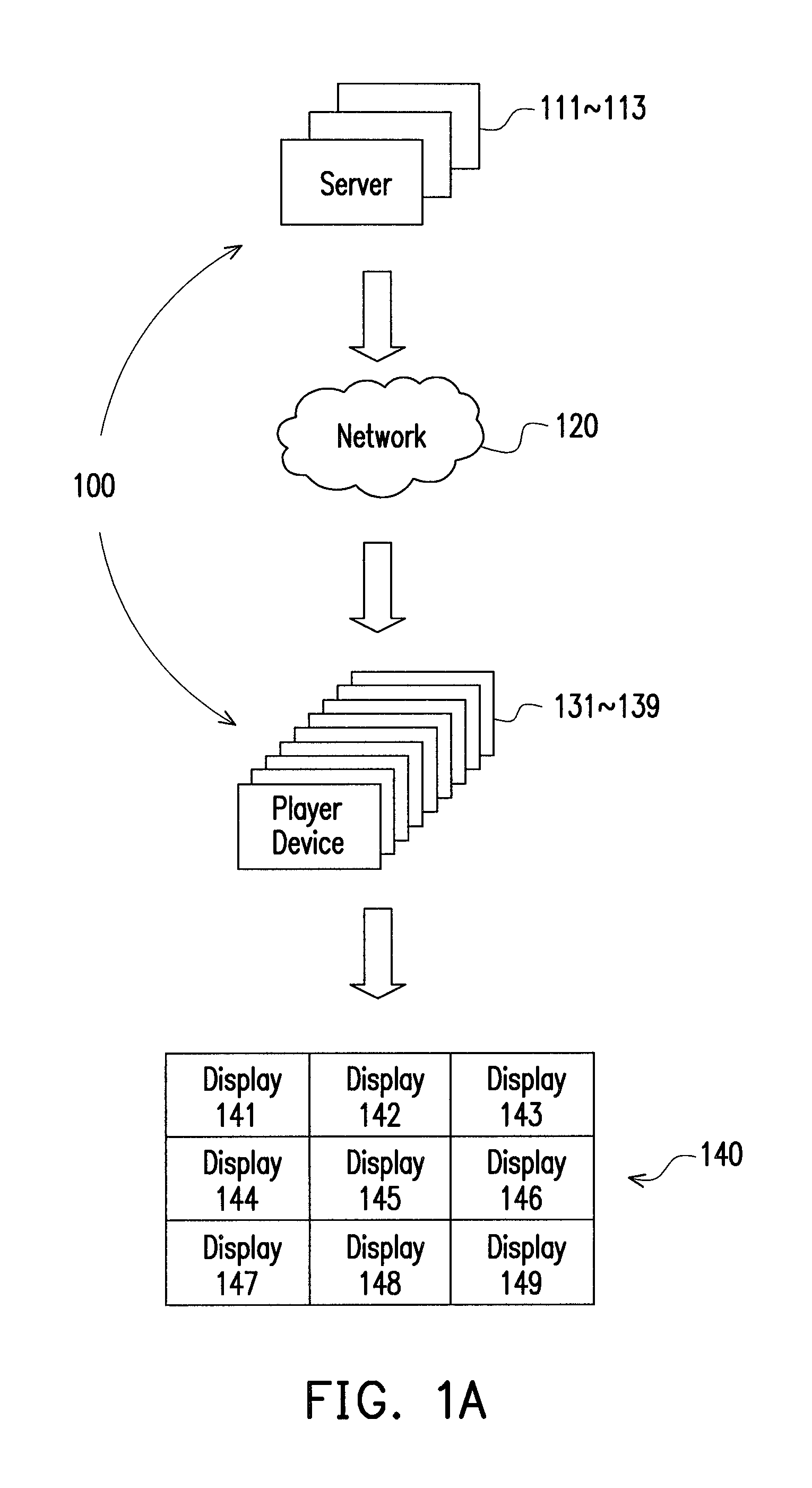
[0023]FIG. 1A is a schematic diagram illustrating a display system 100 according to an embodiment of the invention. The display system 100 of the invention may include at least one server and any amount of player device. In the present embodiment, the display system 100 includes three servers 111 to 113 and nine player devices 131 to 139. Wherein, the servers 111 to 113 each renders an image and transmits the image to a network 120. The network 120 may be a wired network or a wireless network, may be an Internet or a local area network, but the invention is not limited thereto.

[0024]The nine player devices 131 to 139 are coupled to the three servers 111 to 113 through the network 120. Wherein, each player device in the nine player devices 131 to 139 may receive a part of the image rendered by one of the servers 111 to 113 from the network 120. Afterward, each of the player devices 131 to 139 determines a synchronization time together with at least one of the other player devices, an...


PUM


Abstract

A display system and a display method for video walls are provided. The display system includes at least one server and a plurality of player devices. Each server renders an image and transmits the image to a network. The player devices are coupled to the at least one server through the network. Each player device receives the image or a part of the image rendered by one of the at least one server, and determines a synchronization time together with at least one of the other player devices. Each player device uses a display of a video wall to simultaneously display the image or the part of the image at the synchronization time.

Description

CROSS-REFERENCE TO RELATED APPLICATION[0001]This application claims the priority benefit of China application serial no. 201210370806.0, filed on Sep. 28, 2012. The entirety of the above-mentioned patent application is hereby incorporated by reference herein and made a part of this specification.BACKGROUND[0002]1. Field of the Invention[0003]The invention relates to a display system and a display method, and more particularly to, a display system and a display method for video walls.[0004]2. Description of Related Art[0005]A video wall is namely a large display device composed by a plurality of displays via splicing method, and may adapted to be used in a control room, a video conference, or as an indoor / outdoor large billboard.[0006]Conventional methods for the video wall are mostly using a plurality of servers with ×86 frameworks to provide an image displayed by video wall. Each server may use a graphics card of multiple outputs to concurrently connect to the plurality of displays...

Claims


Application Information

Patent Timeline
Patent Type & Authority Patents(United States)
IPC IPC(8): A63F9/24
CPCG07F17/3211G07F17/3227G07F17/3225
Inventor LIU, STEVE, SHU
Owner VIA TECH INC
Why Eureka
Try Eureka