
Knife having resilient elements for blade positioning

a resilient element and blade technology, applied in the field of knives, can solve the problems of increasing the time and space required, the smoothness of the knife b>1/b> is still not smooth and intuitive, and the complexity of the improved structure is often very large, so as to achieve convenient and easy use, the effect of improving the smoothness of operation

Active Publication Date: 2013-07-11
LIAO SHUN YI
View PDF14 Cites 14 Cited by
  • Summary
  • Abstract
  • Description
  • Claims
  • Application Information

AI Technical Summary

Benefits of technology

The present invention is a new type of folding knife with resilient elements that help position the blade. This new knife solves the problem of conventional knives having a large angle at which the blade must rotate to extend, which causes smoothness of operation to be affected. The new knife is more convenient and easy to use for the general public.

Problems solved by technology

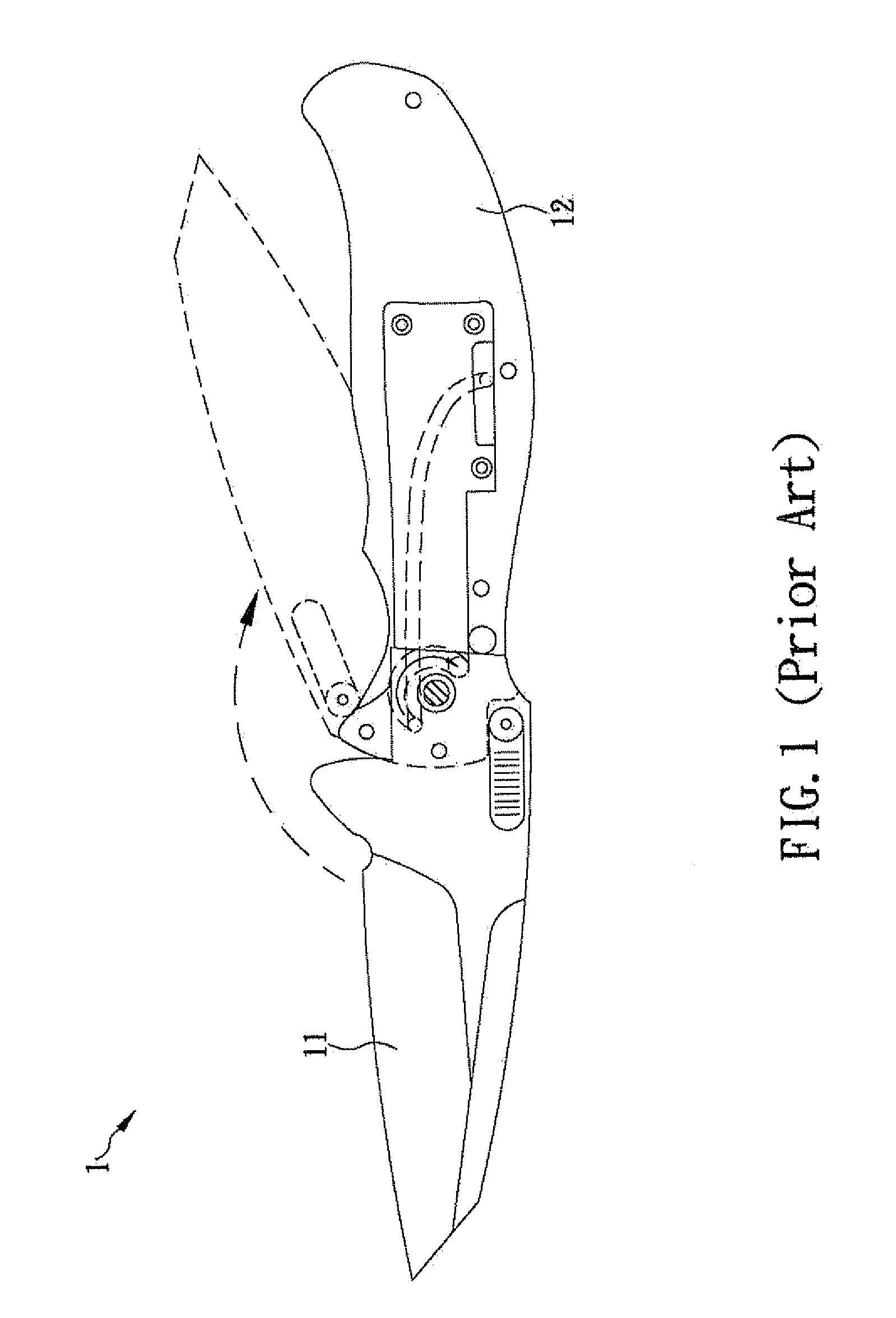
(1) Low smoothness of operation: To use the assisted-opening folding knife 1, the blade 11 must be actuated to rotate at least 180 degrees so as to extend out of the handle 12. However, the longer the rotation path of the blade 11 is, the more the time and space required will be. Therefore, despite improvements made to the actuating mechanism, operation of the knife 1 is still not smooth and intuitive enough. Moreover, for those who are not familiar with the use of knives, the large rotation of the blade 11 tends to cause cut injury to the hand, which raises safety issues in use. Because of the above, assisted-opening folding knives like the knife 1 have yet to be extensively used.
(2) Structural complexity: As previously mentioned, the industry has made improvements to the structure of the assisted-opening folding knife 1 to enhance smoothness of use. Nevertheless, the improved structure is often a very complicated one because the design of the internal structure of the knife 1 must also take into account the positioning stability of the blade 11, the rotation space of the blade 11, and the way in which and the position at which the blade 11 is to be pushed. Consequently, not only is production cost increased, but also the durability of the knife is impaired.

Method used


Image

  • Knife having resilient elements for blade positioning
  • Knife having resilient elements for blade positioning
  • Knife having resilient elements for blade positioning

Examples


Embodiment Construction

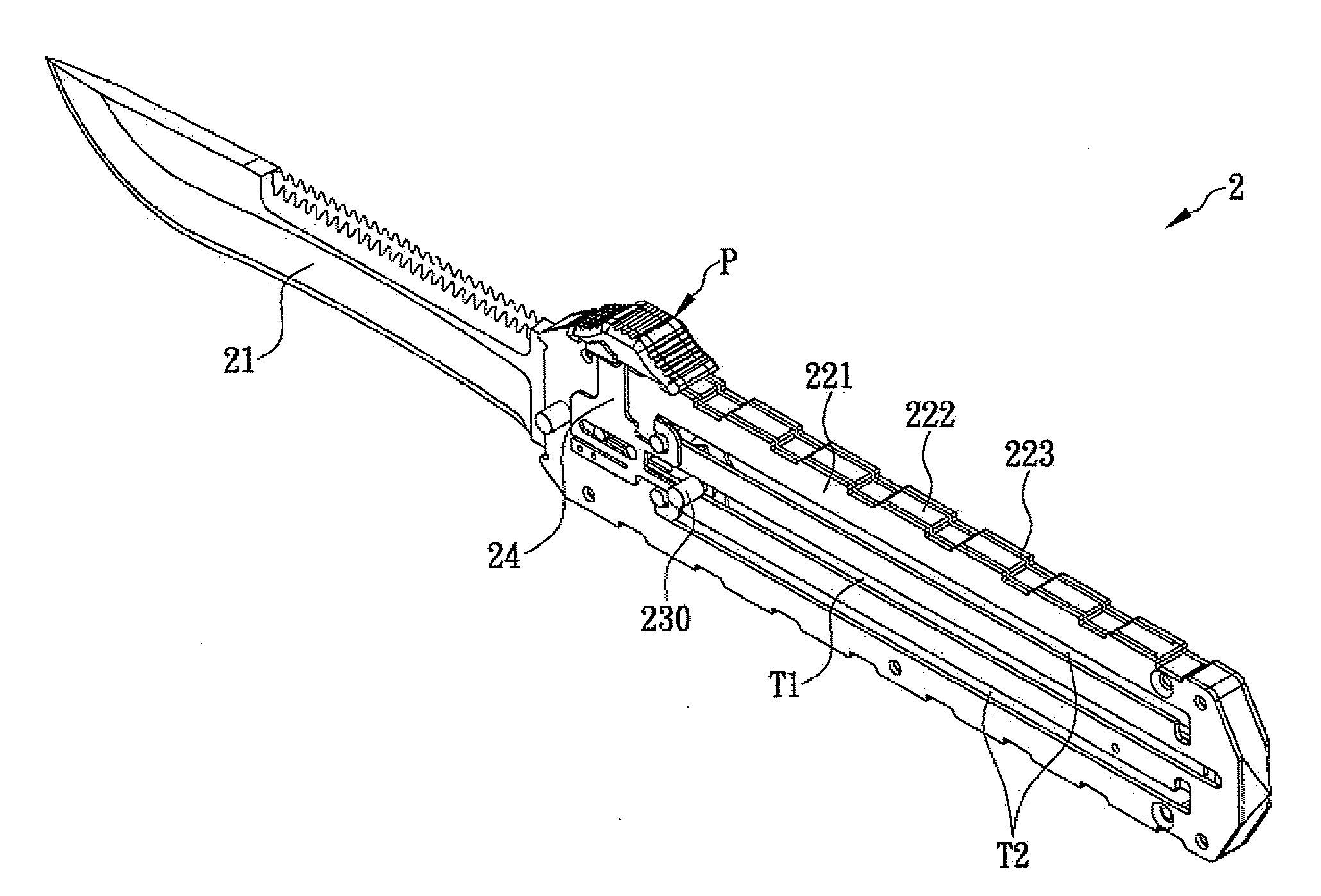
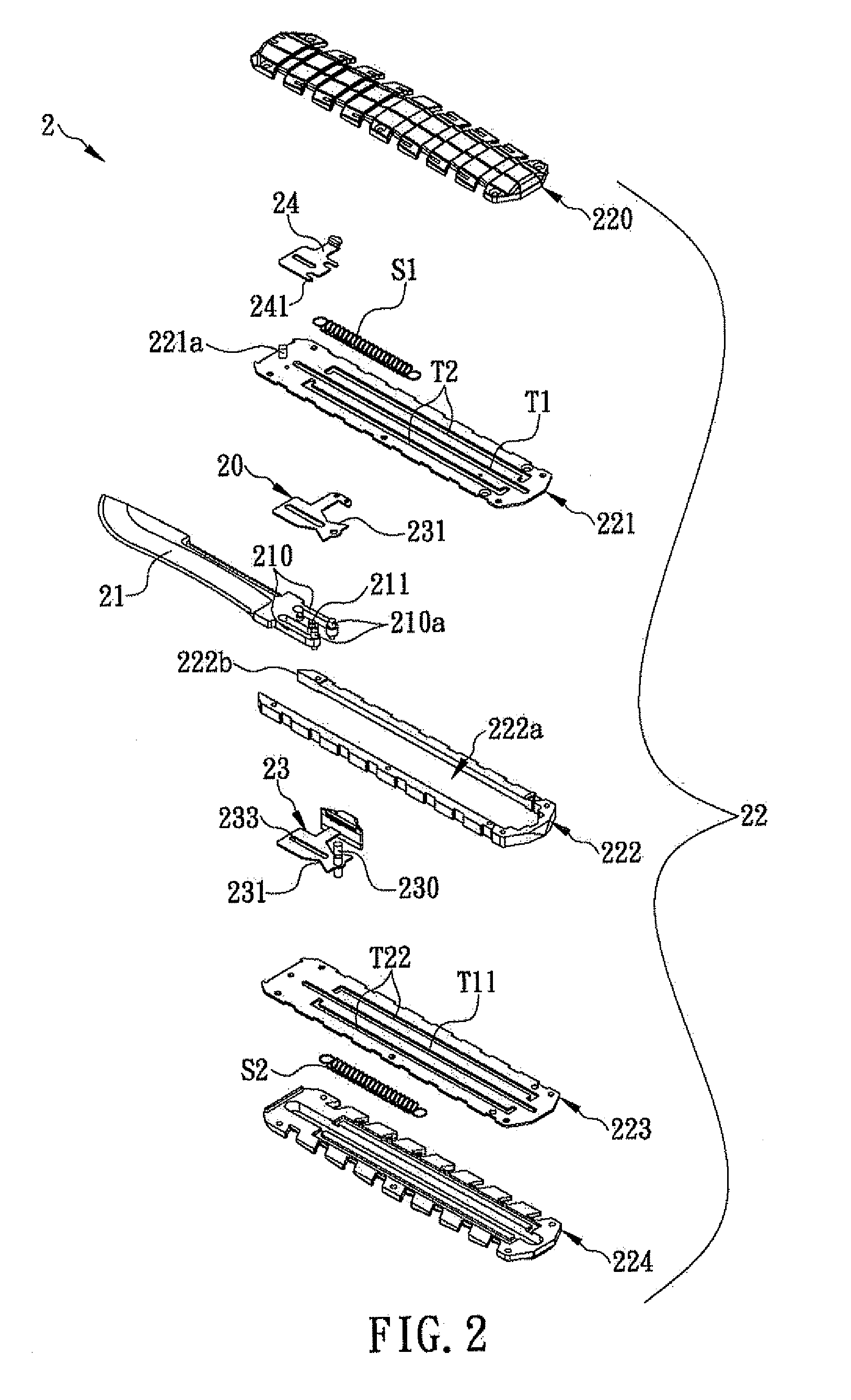
[0020]The present invention discloses a knife having resilient elements for blade positioning. Please refer to FIG. 2 for the first preferred embodiment of the present invention. The knife 2 includes a blade 21, a handle 22, and a pushing element 23. The end of the blade 21 that is away from the blade tip is provided with two resilient elements 210 that extend outward. The very end of the blade 21 is also extendedly provided with at least one projection 211 on each of the top side and the bottom side. Each resilient element 210 has one end protrudingly provided with two engaging portions 210a that extend upward and downward respectively. In this embodiment, the engaging portions 210a on the same side of the resilient elements 210 are spaced by a distance less than the distance between the middle sections of the resilient elements 210. The handle 22 is composed of an upper housing 220, a first plate 221, a middle housing 222, a second plate 223, and a lower housing 224. The middle ho...


PUM


Abstract

The present invention is to provide a knife including a blade and a handle, wherein the blade has a first end provided with a projection and two resilient elements, each resilient element has one end protrudingly provided with an engaging portion, and the handle has a receiving space for receiving the blade and has a first track and two second tracks provided longitudinally thereon. The projection can be movably inserted in the first track. The distance between each pair of the corresponding ends of the second tracks corresponds to the distance between the engaging portions. Thus, when the engaging portions are respectively engaged in a pair of the corresponding ends of the second tracks, the engaging portions cannot move along the second tacks, such that either the blade is completely received and positioned in the handle, or a second end of blade is extended and positioned outside the handle.

Description

FIELD OF THE INVENTION[0001]The present invention relates to a knife, more particularly to a knife including a blade having a first end provided with two resilient elements, wherein each of the resilient elements has one end protrudingly provided with an engaging portion. Thus, when the engaging portions are respectively engaged in a pair of corresponding ends of two second tracks longitudinally provided on the handle, the engaging portions cannot move along the second tacks such that either the blade is completely received and positioned in the handle, or a second end of blade is extended and positioned outside the handle.BACKGROUND OF THE INVENTION[0002]Recently, with the advancement of craft techniques and the improvement of living standards, people who intend to buy a new product consider not only the price and durability of the product, but also whether the product is convenient and safe to use. Such a change in market trends has driven manufacturers and designers in all fields...

Claims


Application Information

Patent Timeline
IPC IPC(8): B26B1/08
CPCB26B1/08B26B5/001
Inventor LIAO, SHUN-YI
Owner LIAO SHUN YI
Learn More