Optical communication network path restoration

Active Publication Date: 2013-07-11
CIENA
View PDF15 Cites 34 Cited by
  • Summary
  • Abstract
  • Description
  • Claims
  • Application Information

AI Technical Summary

Problems solved by technology

Setting up a connection in an optical network is more complicated than setting up a connection in a digital network.
For example, retuning a lase

Method used


Image

  • Optical communication network path restoration
  • Optical communication network path restoration
  • Optical communication network path restoration

Examples


Embodiment Construction

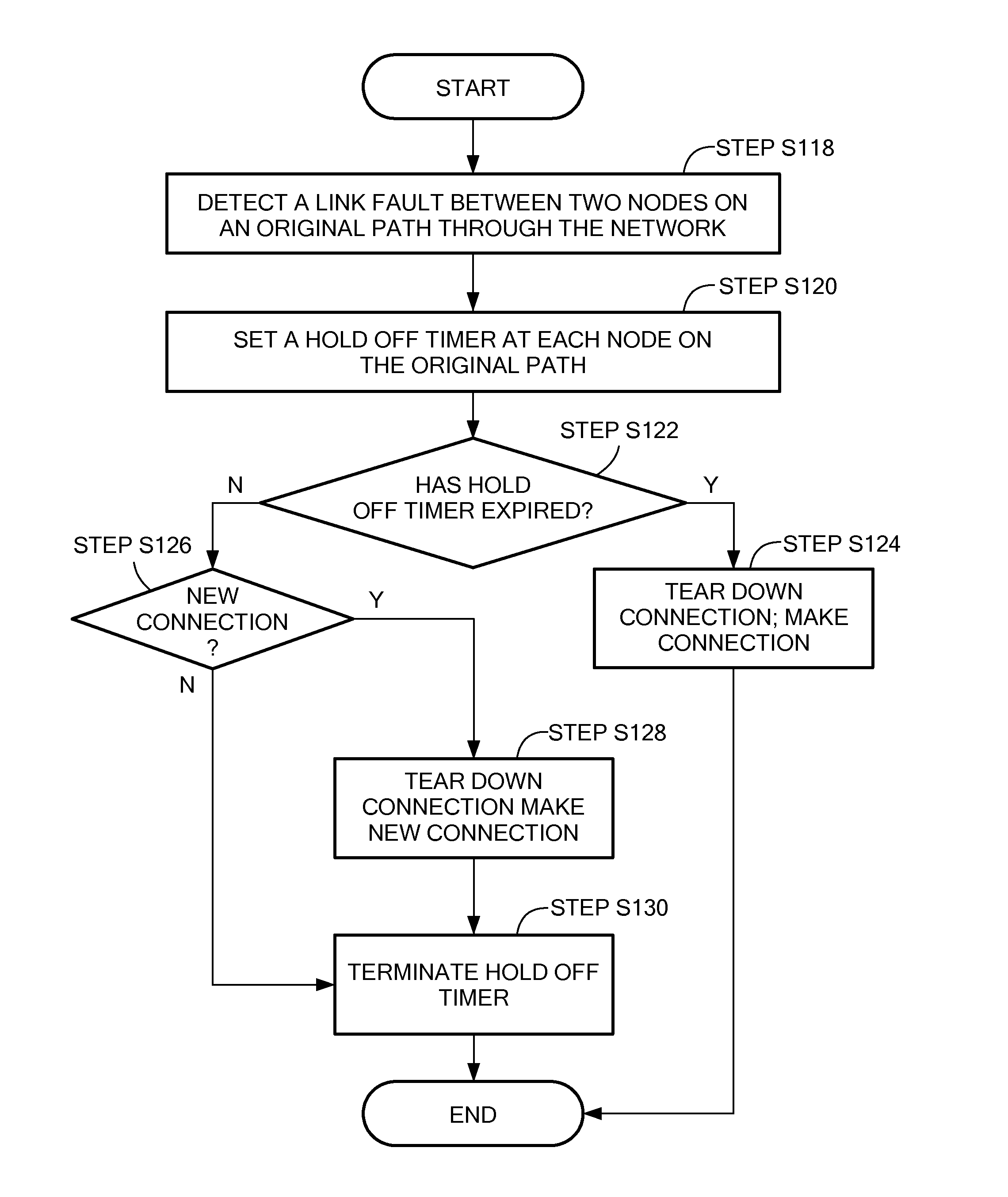
[0017]Before describing in detail exemplary embodiments that are in accordance with the present invention, it is noted that the embodiments reside primarily in combinations of apparatus components and processing steps related to establishing a new path through an optical network from source node to a destination node when a link failure occurs on an original path. Accordingly, the system and method components have been represented where appropriate by conventional symbols in the drawings, showing only those specific details that are pertinent to understanding the embodiments of the present invention so as not to obscure the disclosure with details that will be readily apparent to those of ordinary skill in the art having the benefit of the description herein.

[0018]As used herein, relational terms, such as “first” and “second,”“top” and “bottom,” and the like, may be used solely to distinguish one entity or element from another entity or element without necessarily requiring or imply...


PUM


Abstract

A method and system of determining a new path through an optical network from a source node to a destination node when a link in an original path fails are disclosed. When a fault on a link is detected, adjoint weights are assigned to each operational link for each node on the original path. A connection cost is determined for each node based on the adjoint weights of the links connected to the node. A new path through the optical network is determined based at least in part on the adjoint weights and the connection costs.

Description

CROSS-REFERENCE TO RELATED APPLICATION[0001]This application relates to and claims priority to Indian Patent Application Serial Number 42 / DEL / 2012, filed Jan. 5, 2012, the entirety of which is incorporated herein by reference.STATEMENT REGARDING FEDERALLY SPONSORED RESEARCH OR DEVELOPMENT[0002]n / aFIELD OF THE INVENTION[0003]The present invention relates to optical networking, and more particularly to a method and system for establishing a restoration path in an optical network.BACKGROUND OF THE INVENTION[0004]Service provisioning in an optical network includes establishing a restoration connection when a fault in a link of an existing path occurs. Typically, in an optical network, when a fault in a link occurs, each connection along the original path is torn down and new connections are set up to reestablish the path. Setting up a connection in an optical network is more complicated than setting up a connection in a digital network. As an example, establishing a new connection in an...

Claims


Application Information

Patent Timeline
IPC IPC(8): H04B10/00
CPCH04J14/0269H04J14/0268
Inventor PRAKASH, ANURAGCHHILLAR, MOHITTRNKUS, MARIAN
Owner CIENA
Why Eureka
Try Eureka