Material deposition system and method for depositing materials on a substrate

a technology of material deposition and substrate, applied in the direction of resistive material coating, liquid/solution decomposition chemical coating, superimposed coating process, etc., can solve the problem of reducing the efficiency of the dispensing process, affecting the dispensing speed, and no known ink jetting method, etc. problem, to achieve the effect of high velocity

Active Publication Date: 2013-07-11
ILLINOIS TOOL WORKS INC
View PDF2 Cites 21 Cited by
  • Summary
  • Abstract
  • Description
  • Claims
  • Application Information

AI Technical Summary

Problems solved by technology

The process of wetting contributes to additional time to perform the dispensing operation.
Thus, traditional ink jet systems are not particularly suited for dispensing the more viscous materials described above.
However, for jetting higher viscosity liquids (greater than 100 centipoise) with drop-on-demand requirement, there is no known ink jetting method.
However, such prior art drop-on-demand ink jet heads suffer from numerous disadvantages, drawbacks and / or limitations, for example as discussed in U.S. Pat. No. 4,613,875, entitled AIR ASSISTED INK JET HEAD WITH PROJECTING INTERNAL INK DROP-FORMING ORIFICE OUTLET, and in U.S. Pat. No. 4,728,969, entitled AIR ASSISTED INK JET HEAD WITH SINGLE COMPARTMENT INK CHAMBER, the entire disclosures of these patents are herein incorporated by reference.
The existing micro-jetting technology, whether it is piezo-jet, positive displacement or time pressure has inherent limitations on droplet size and fluid viscosity range for suitable jetted fluids, and therefore have not been successfully incorporated into dispensers and systems for applying such viscous materials onto electronic substrates.

Method used


Image

  • Material deposition system and method for depositing materials on a substrate
  • Material deposition system and method for depositing materials on a substrate
  • Material deposition system and method for depositing materials on a substrate

Examples


Embodiment Construction

[0030]For the purposes of illustration only, and not to limit the generality, the present disclosure will now be described in detail with reference to the accompanying figures. This disclosure is not limited in its application to the details of construction and the arrangement of components set forth in the following description or illustrated in the drawings. The principles set forth in this disclosure are capable of other embodiments and of being practiced or carried out in various ways. Also the phraseology and terminology used herein is for the purpose of description and should not be regarded as limiting. The use of “including,”“comprising,”“having,”“containing,”“involving,” and variations thereof herein, is meant to encompass the items listed thereafter and equivalents thereof as well as additional items.

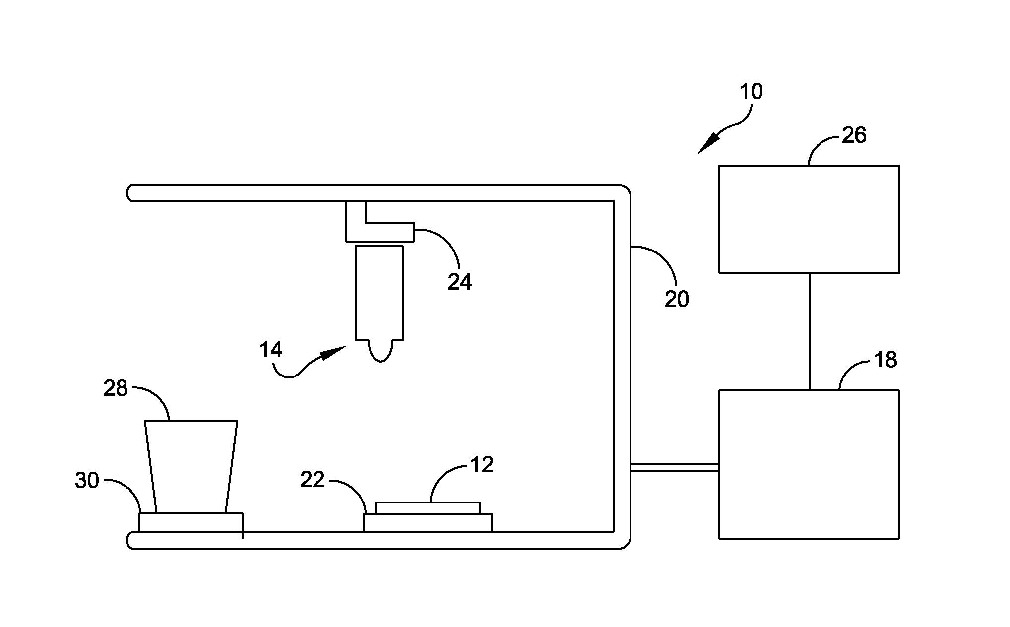
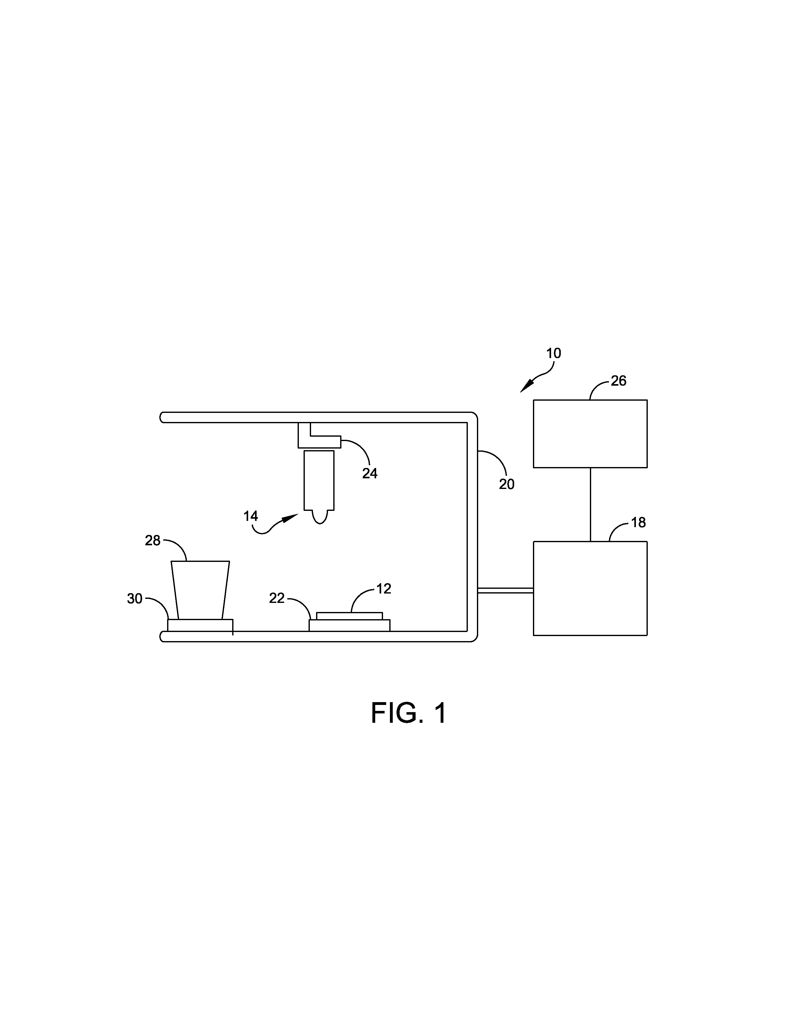
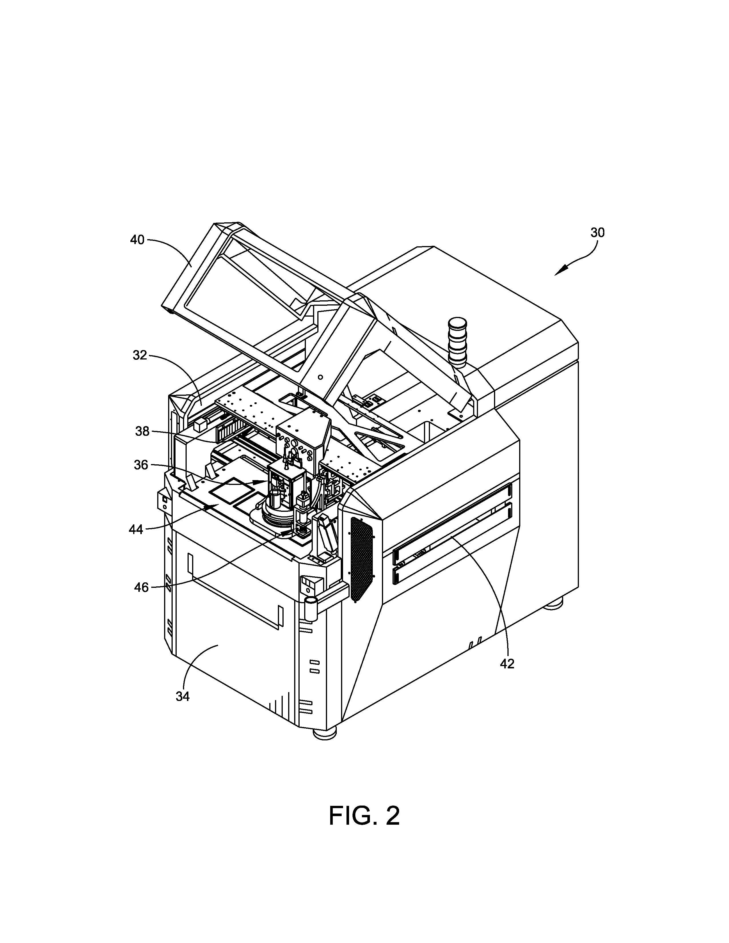
[0031]Various embodiments of the present disclosure are directed to material deposition or application systems, devices including such material deposition system, and methods ...


PUM

PropertyMeasurementUnit
viscosityaaaaaaaaaa
viscosityaaaaaaaaaa
sound velocityaaaaaaaaaa

Abstract

A material deposition system includes a frame, a support coupled to the frame to support an electronic substrate during a deposit operation, a gantry coupled to the frame, and a deposition head coupled to the gantry. The deposition head is movable over the support by movement of the gantry. The deposition head includes a chamber to hold material, an actuator to push a volume of material out of the chamber, a needle extending from the chamber and terminating in a needle orifice, and at least two air jets located on opposite sides of the needle orifice. A desired volume of material is formed at the needle orifice in response to the actuator, and each of the at least two air jets produce a timed pulse of air to create a micro-droplet from the desired volume and to accelerate the micro-droplet to high velocity.

Description

RELATED APPLICATIONS[0001]This patent application is a Continuation patent application of U.S. Ser. No. 13 / 448,721, entitled “Material Deposition System and Method for Depositing Materials on a Substrate,” filed on Apr. 17, 2012, which claims priority to U.S. patent application entitled “Pulsed Air-Actuated Micro-Droplet on Demand Ink Jet” filed Jun. 29, 2011 and assigned U.S. application Ser. No. 13 / 135,215, and to U.S. Provisional patent application entitled “Pulsed Air-Actuated Micro-Droplet on Demand Ink Jet” filed Aug. 25, 2010 and assigned U.S. Application Ser. No. 61 / 376,942, all of which are hereby herein incorporated by reference in their entirety for all purposes.BACKGROUND OF THE DISCLOSURE[0002]1. Field of the Disclosure[0003]This disclosure relates generally to systems and methods for depositing a material on a substrate, such as a printed circuit board, and more particularly to an apparatus and a method for depositing materials, such as solder paste, epoxies, underfill...

Claims


Application Information

Patent Timeline
Patent Type & Authority Applications(United States)
IPC IPC(8): H05K3/00
CPCB41J2/045B41J2202/02H05K2203/11B41J2/14H05K3/0091
Inventor CROUCH, KENNETH C.KWOK, KUI-CHIUTRACY, ROBERT W.MOHANTY, RITAKARLINSKI, THOMAS J.REID, SCOTT A.
Owner ILLINOIS TOOL WORKS INC
Why Eureka
Try Eureka