
Pneumatic impact tool with a spindle positioning device

a technology of positioning device and pneumatic impact tool, which is applied in the direction of screwing, threaded fasteners, manufacturing tools, etc., can solve the problems of reducing the service life of pneumatic impact tool, affecting the smooth rotation of the spindle,

Active Publication Date: 2013-07-18
BASSO IND CORP
View PDF13 Cites 1 Cited by
  • Summary
  • Abstract
  • Description
  • Claims
  • Application Information

AI Technical Summary

Benefits of technology

The invention is a pneumatic impact tool with a spindle positioning device that prevents the bushing from moving in the housing and allows for easy replacement, repair, and maintenance of the spindle and output shaft. The device includes a bushing and a stop pin that prevents the bushing from moving in the housing. The stop pin is removable and engages with the frustoconical outer surface of the bushing to prevent movement. The technical effect of this invention is to effectively prevent movement of the bushing and ensure the stability of the spindle positioning device.

Problems solved by technology

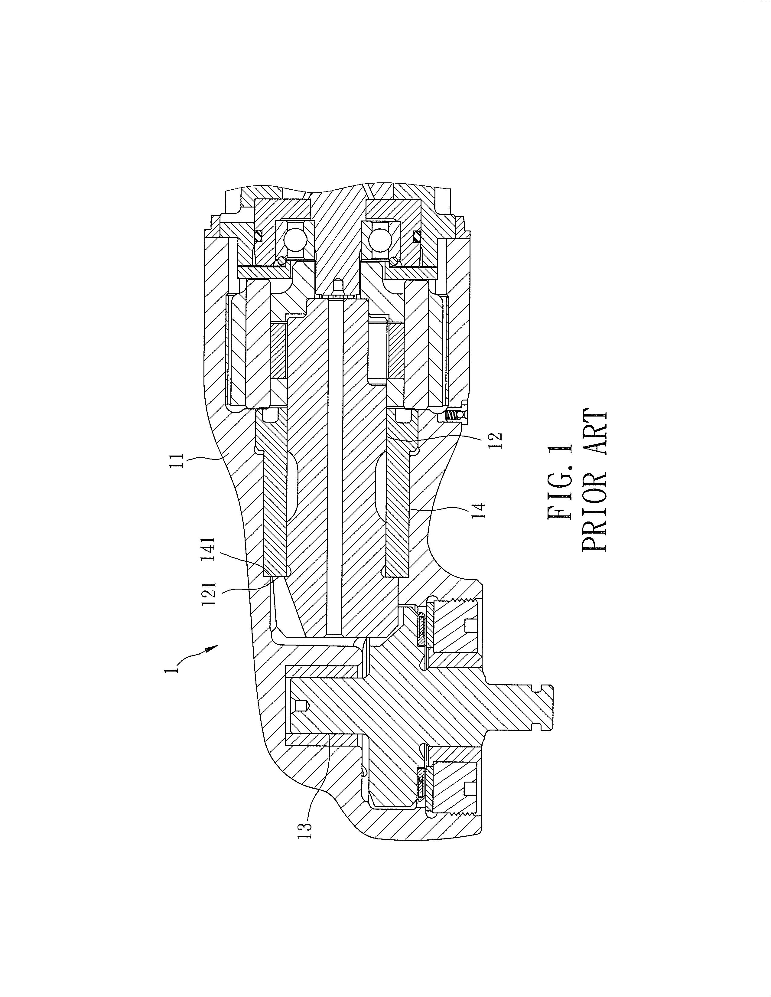
However, since the bushing 14 is just threaded to the housing 11, during power transmission, the spindle 12 pushes the bushing 14 to move in the housing 11 in a direction away from the output shaft 13 due to reaction force coming from the output shaft 13, thereby resulting in a change to the distance between the spindle 12 and the output shaft 13, which affects adversely smooth rotation of the spindle 12 and the output shaft 13 and reduces the service life of the pneumatic impact tool 1.

Method used


Image

  • Pneumatic impact tool with a spindle positioning device
  • Pneumatic impact tool with a spindle positioning device
  • Pneumatic impact tool with a spindle positioning device

Examples


Embodiment Construction

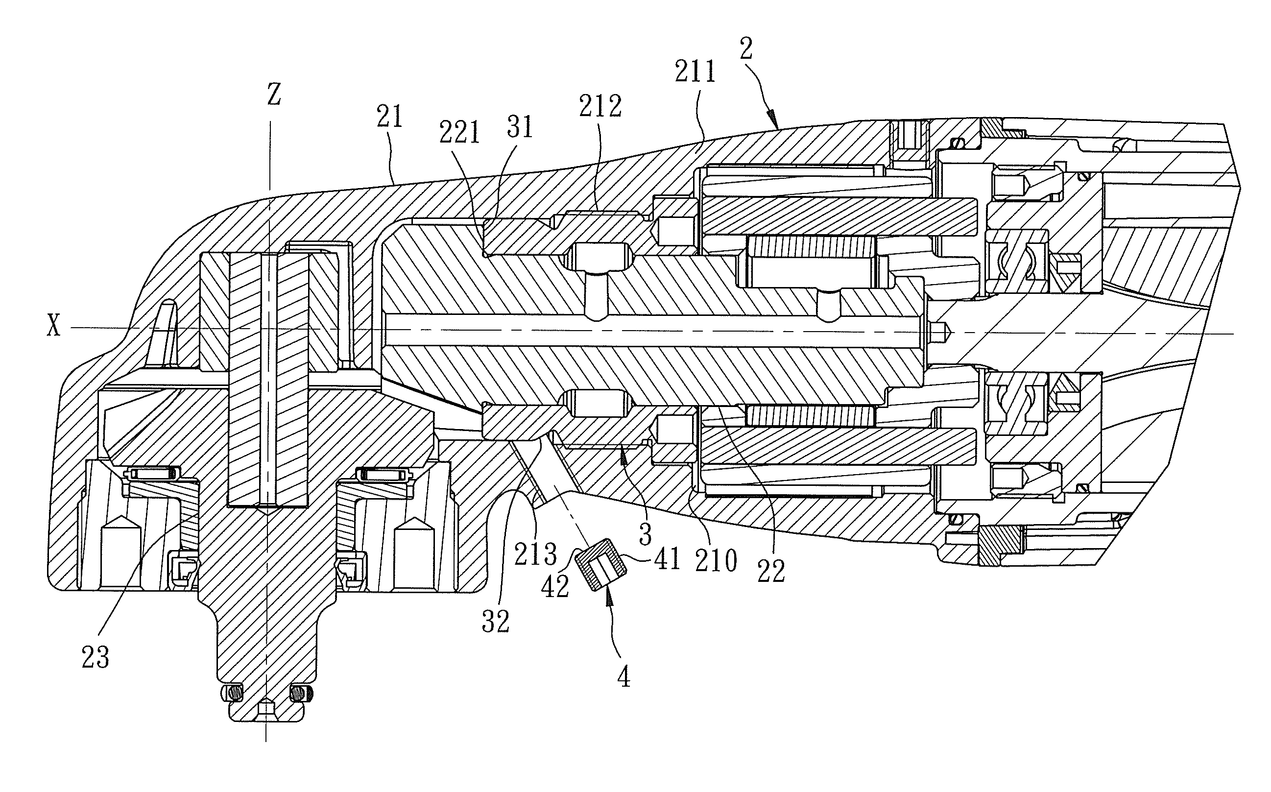
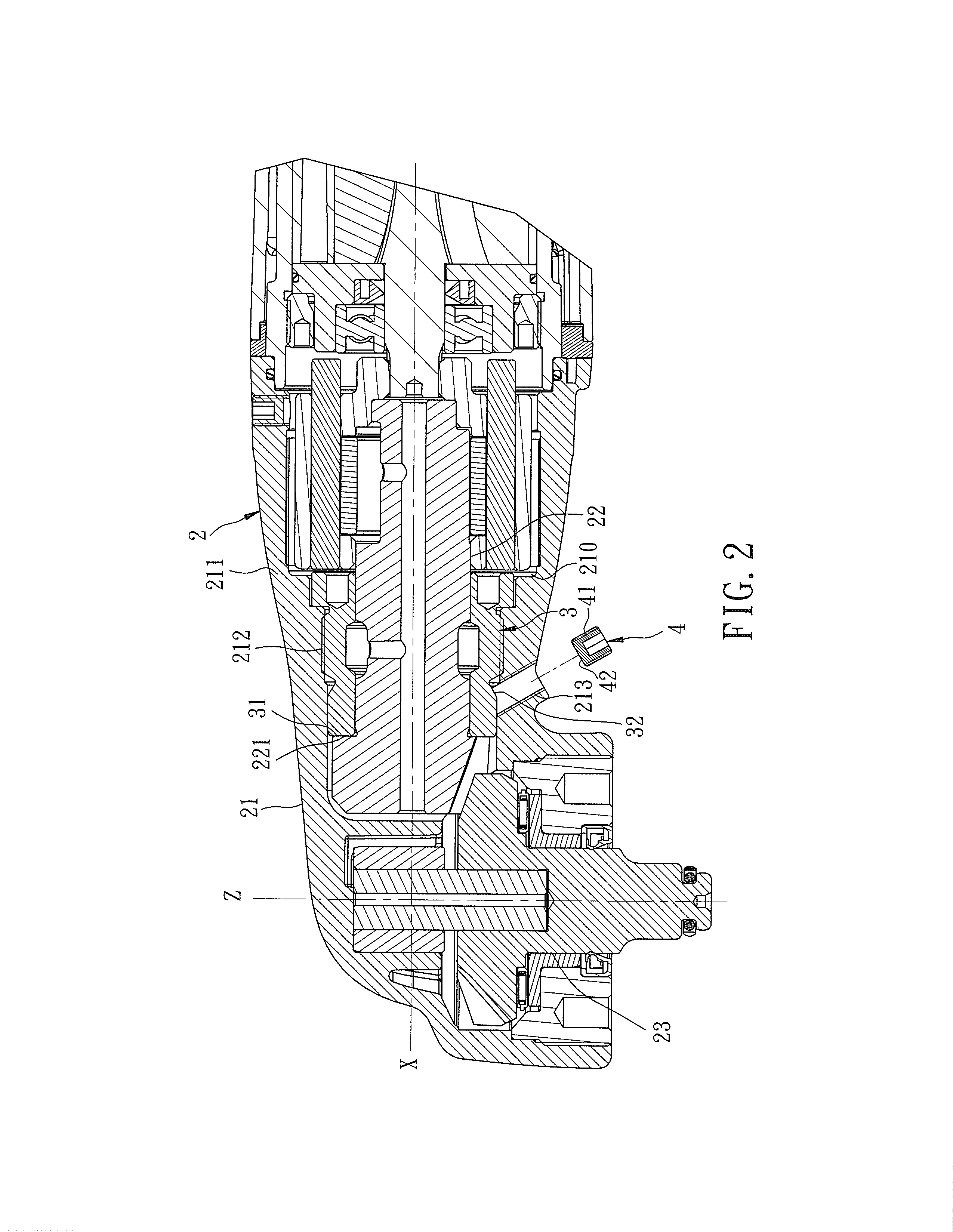
[0018]Referring to FIGS. 2 and 3, the preferred embodiment of a pneumatic impact tool 2 according to this invention includes a housing 21, a spindle 22, an output shaft 23, and a spindle positioning device. The housing 21 has a housing wall 211 defining an accommodating chamber 210, an inner threaded hole 212 defined by an inner surface of the housing wall 211, and an inclined threaded hole 213 formed through the housing wall 211. The spindle 22 extends along an X-axis, and is disposed rotatably in the accommodating chamber 210 of the housing 21 for power transmission. The output shaft 23 extends along a Z-axis, is disposed in the accommodating chamber 210 of the housing 21, and is geared to the spindle 22 for outputting a power. The spindle 22 has a position-limiting surface 221 parallel to the Z-axis. The spindle positioning device includes a bushing 3 and a stop pin 4.

[0019]The bushing 3 extends along the X-axis in the accommodating chamber 210, is threaded in the inner threaded ...


PUM


Abstract

A pneumatic impact tool includes a spindle extending along an X-axis, an output shaft extending along a Z-axis, and a spindle positioning device that includes a bushing and a stop pin. The bushing is threaded in a housing, and has a stop surface and a frustoconical outer surface. The stop surface obstructs the spindle from moving away from the output shaft. The frustoconical outer surface has opposite first and second ends. The first end is nearer to the X-axis and farther away from the Z-axis than the second end. The stop pin is disposed removably in the housing, and has an engaging surface abutting against the frustoconical outer surface, so as to prevent the bushing from moving in the housing in a direction away from the output shaft.

Description

CROSS-REFERENCE TO RELATED APPLICATION[0001]This application claims priority of Taiwanese Application No. 101201059, filed on Jan. 17, 2012.BACKGROUND OF THE INVENTION[0002]1. Field of the Invention[0003]This invention relates to a positioning device, and more particularly to a spindle positioning device for a pneumatic impact tool.[0004]2. Description of the Related Art[0005]Referring to FIG. 1, a conventional pneumatic impact tool 1 disclosed in US2011 / 0139474A1 includes: a housing 11; a spindle 12 disposed rotatably in the housing 11 and extending along an X-axis for power transmission; an output shaft 13 disposed rotatably in the housing 11, geared to the spindle 12, and extending along a Z-axis perpendicular to the X-axis for outputting a power; and a bushing 14. The spindle 12 has a position-limiting surface 121 parallel to the Z-axis. The bushing 14 is threaded in the housing 11, and has an end surface or stop surface 141 abutting against the position-limiting surface 121.[00...

Claims


Application Information

Patent Timeline
IPC IPC(8): B25D17/00
CPCB25D17/00F16B35/005B25B21/02
Inventor SU, SAN-YIHLAI, CHENG-WEI
Owner BASSO IND CORP
Learn More