Image forming apparatus and control method thereof

a technology of image forming apparatus and control method, which is applied in the direction of electrographic process apparatus, instruments, optics, etc., can solve the problems of memory part damage, difficulty in managing the lifespan of the various components installed at the image forming apparatus, etc., and achieve the effect of effectively managing the information on the lifespan of consumable products

Active Publication Date: 2013-07-18
HEWLETT PACKARD DEV CO LP
View PDF2 Cites 12 Cited by
  • Summary
  • Abstract
  • Description
  • Claims
  • Application Information

AI Technical Summary

Benefits of technology

[0030]As described above, since the information of the lifespan of the consumable product is stored at a separate memory device, which is detachably coupled to a main board, in the form of a backup, even in a case when the main board needs to be replaced due to a defect of the main board, initialization of the information of the lifespan of the consumable product may be prevented from occurring.
[0031]In addition, as a separate memory device is detached from a conventional main board to mount the separate memory device on a replaced main board, a convenience is achieved during the replacement task of the main board.
[0032]In addition, since the information on the consumable product is stored at a plurality of memory devices, even in a case when a certain one of the plurality of memory devices is hacked, the information on the lifespan of the consumable product may be effectively managed.

Problems solved by technology

However, when replacing the main board with a new main board in a case of a defect generated at the main board, the information with reference to the lifespan of the consumable product, which is calculated and stored in the meantime, is initialized, and thus, a difficulty of being unable to manage the lifespan of the various components installed at the image forming apparatus occurs.
Meanwhile, as to resolve such difficulties, a method of separately removing a non-volatile memory part provided at the conventional main board, and reattaching the non-volatile memory part on a replaced main board is known, but this method is provided with an inconvenience in performing a replacement task of the non-volatile memory part, and during the replacement process of the non-volatile memory part, if a mistake by a user occurs (a service technician), the memory part may be damaged.

Method used


Image

  • Image forming apparatus and control method thereof
  • Image forming apparatus and control method thereof
  • Image forming apparatus and control method thereof

Examples


Embodiment Construction

[0042]Reference will now be made in detail to the embodiments of the present general inventive concept, examples of which are illustrated in the accompanying drawings, wherein like reference numerals refer to the like elements throughout. The embodiments are described below in order to explain the present general inventive concept while referring to the figures.

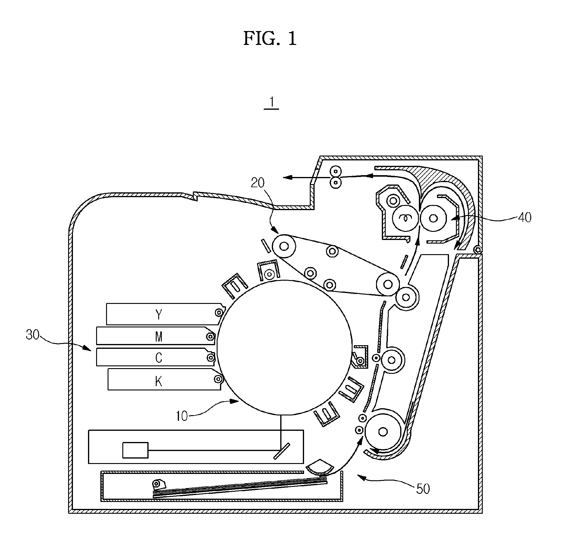
[0043]FIG. 1 is a side cross-sectional view schematically illustrating an engine structure of an image forming apparatus in accordance with an embodiment of the present disclosure.

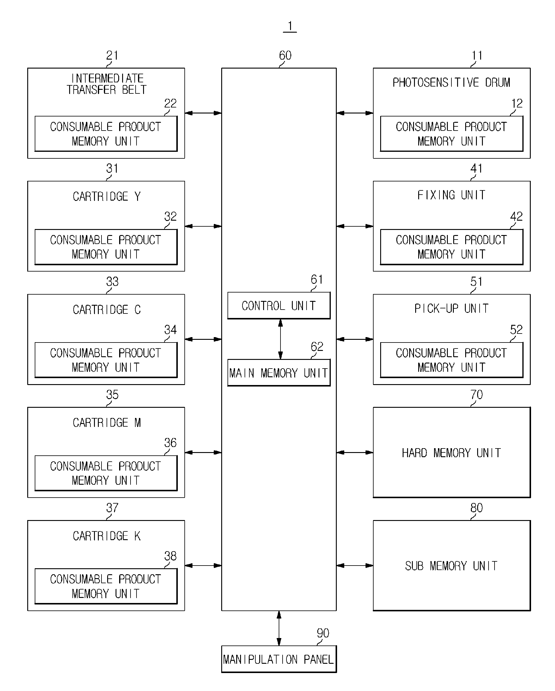
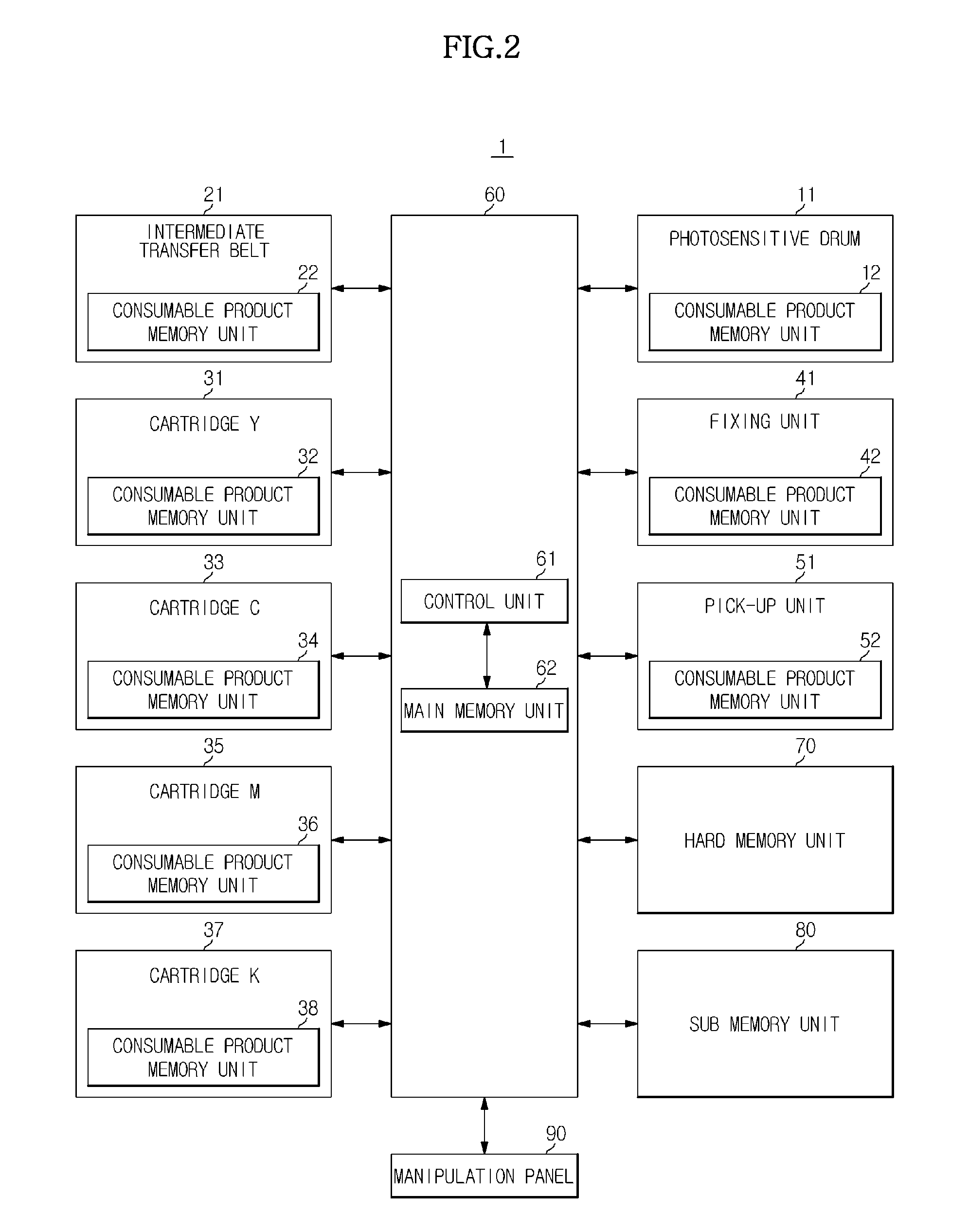
[0044]Referring to FIG. 1, an image forming apparatus 1 using an electro-photographing method includes a photosensitive unit 10, a developing unit 30, an intermediate transfer unit 20, a fixing unit 40, and a pick-up unit 50.

[0045]The photosensitive unit 10 includes a photosensitive medium, and the photosensitive medium is referred to as a photosensitive drum 11 formed of a cylindrical metallic drum and having a conductive layer on an outer circumfe...


PUM


Abstract

An image forming apparatus configured to form a color image by having at least one consumable product, the image forming apparatus including a main board, a first memory unit detachably coupled to the main body, a consumable product memory unit installed at the consumable product, and configured to store information on a lifespan of the consumable product, and a control unit configured to read the information on the lifespan of the consumable product from the consumable product memory unit, and to store the information on the lifespan of the consumable product at the first memory unit in the form of a backup.

Description

CROSS-REFERENCE TO RELATED APPLICATIONS[0001]This application claims the benefit of Korean Patent Application No. 2012-0004656, filed on Jan. 16, 2012, in the Korean Intellectual Property Office, the disclosure of which is incorporated herein by reference in its entirety.BACKGROUND OF THE INVENTION[0002]1. Field of the Invention[0003]Exemplary embodiments of the present disclosure relate to an image forming apparatus configured to manage information with reference to a lifespan of a consumable product, and a control method thereof.[0004]2. Description of the Related Art[0005]In general, an image forming apparatus using an electro-photographing method is an apparatus configured to form an electrostatic latent image on a photosensitive medium using a light exposing unit such as a laser scanning unit (LSU) by receiving image data that corresponds to a desired image, to form a toner image by supplying a toner to the electrostatic latent image by using a developing unit, to transfer the ...

Claims


Application Information

Patent Timeline
Patent Type & Authority Applications(United States)
IPC IPC(8): G03G15/00
CPCG03G15/0863G03G15/553G03G21/1889G03G15/01G03G21/16
Inventor EOM, YOON SEOP
Owner HEWLETT PACKARD DEV CO LP
Why Eureka
Try Eureka