Automated implantable penile prosthesis pump system

a pump system and penile prosthesis technology, applied in the field of automatic pumping system for inflating the inflatable cylinder, can solve the problems of patient discomfort, inability to locate and operate the pump, and inherently more difficult operation of the ipp, so as to reduce the extent and complexity of surgery, and the effect of more precise inflation and pressurization of the pressure cylinder

Active Publication Date: 2013-07-25
BOSTON SCI SCIMED INC
View PDF2 Cites 7 Cited by
  • Summary
  • Abstract
  • Description
  • Claims
  • Application Information

AI Technical Summary

Benefits of technology

[0006]The present invention is directed to an IPP having an inflatable cylinder comprising an integrated inflation system for inflating and pressurizing the inflatable cylinder. The inflation system comprises a piezoelectric pump for drawing fluid from a reservoir integrated into the inflatable cylinder and feeding the fluid into a pressure cylinder to expand and stiffen the inflatable cylinder. The piezoelectric pump and reservoir can be fully contained within the inflatable cylinder significantly reducing the extent and complexity of the surgery required for implanting the IPP. In addition, the automated piezoelectric pump replaces the manually operated mechanical pump used to inflate the inflatable cylinder in conventional IPP allowing for more precise inflation and pressurization of the pressure cylinder. The piezoelectric pump can be wirelessly controlled to control the inflation or deflation of the pressure cylinder.

Problems solved by technology

While fully implanting the IPP within the body provides numerous advantages, operating the IPP is inherently more difficult due to the lack of direct access to the IPP.
In particular, because the pump must be manually actuated through the scrotum, locating and operating the pump can be difficult.
In addition, the position of the pump may cause the patient's to experience discomfort when operating the pump.
An added drawback is that patients with comorbidities affecting their dexterity may be completely unable to operate the pump.
In addition to the practical difficulties of fully implanting the IPP, the implantation and positioning of the various components of the IPP itself can be a deterrent to those considering implanting an IPP.

Method used


Image

  • Automated implantable penile prosthesis pump system
  • Automated implantable penile prosthesis pump system
  • Automated implantable penile prosthesis pump system

Examples


Embodiment Construction

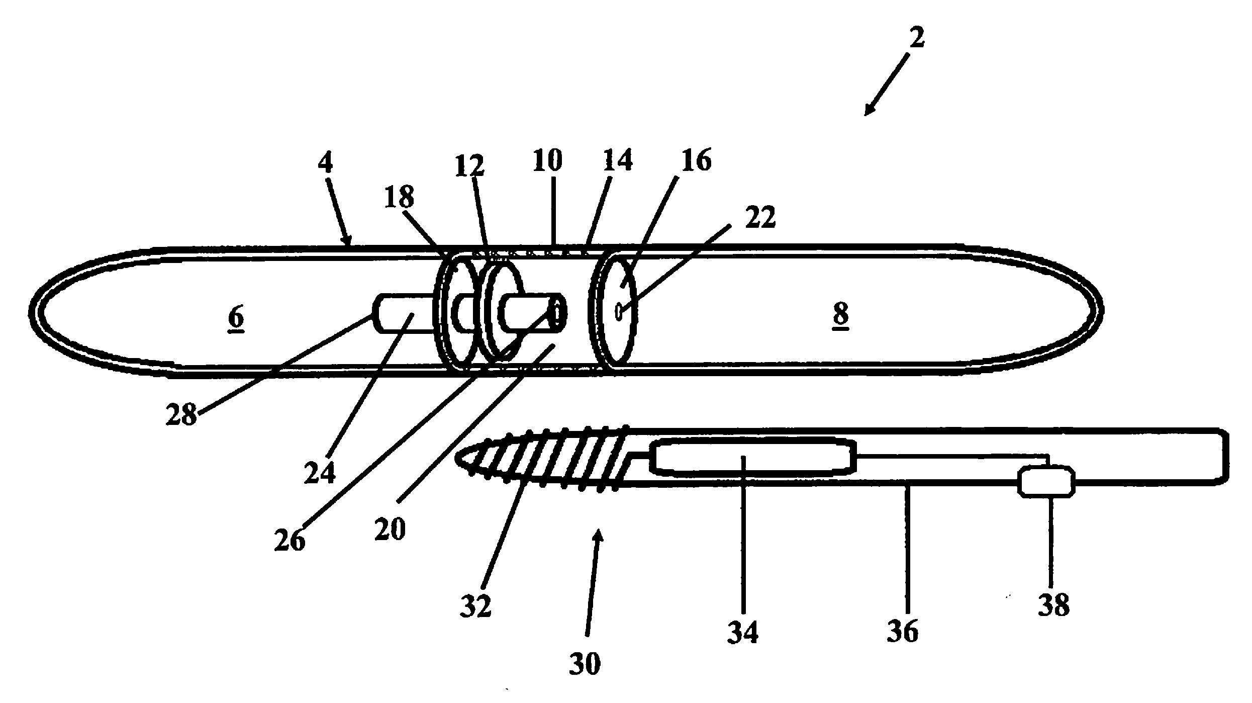
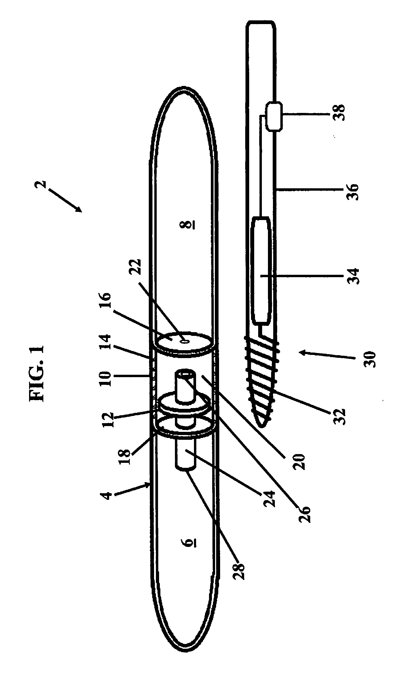
[0016]As shown in FIG. 1, an implantable penile prosthesis 2 (“IPP”), according to an embodiment of the present invention, comprises at least one inflatable cylinder 4 implantable within the corpus cavernosum. Each inflatable cylinder 4 comprises an elongated cylindrical body defining a fluid reservoir 6 at one end and an expandable pressure cylinder 8 positioned opposite the fluid reservoir 6. Each inflatable cylinder 4 further comprises an inflation system 10 operably linking the fluid reservoir 6 to the expandable pressure cylinder 8.

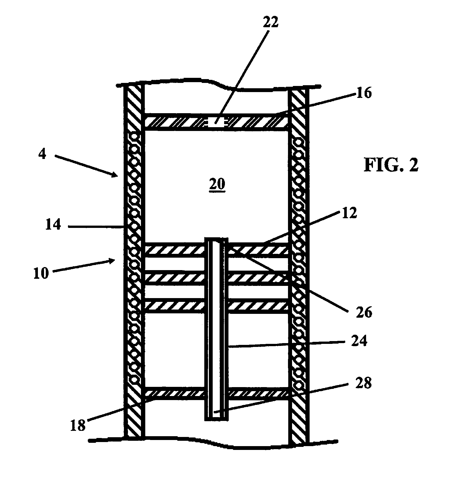
[0017]As shown in FIG. 2, the inflation system 10 further comprises at least one piezoelectric actuator 12 and a pump inductive coil 14. The inflation system 10 further comprises a first septum 16 defining one wall of the pressure cylinder 8 and a second septum 18 defining one wall of the fluid reservoir 6. The first septum 16 and the second septum 18 cooperate to define a pump cavity 20 within the inflatable cylinder 4 between the fluid reservoir 6 ...


PUM


Abstract

An implantable penile prosthesis having an inflatable cylinder with at least one piezoelectric pump for transferring fluid between an integrated reservoir and pressure chamber within the inflatable cylinder. The piezoelectric pump includes an actuator powered by an inductor coil integrated into the inflatable cylinder allowing for wireless control of the inflation and deflation of the inflatable cylinder. An external control system having a corresponding inductive coil can be used to supply a magnetic field for creating a current in the inductor coil integrated into the inflatable cylinder.

Description

RELATED APPLICATION[0001]The present application claims the benefit of U.S. Provisional Application No. 61 / 588,917 filed Jan. 20, 2012, which is incorporated herein in its entirety by reference.FIELD OF THE INVENTION[0002]The present invention is directed a system for inflating at least one inflatable cylinder of an implantable penile prosthesis. Specifically, the present invention is directed an automated pumping system for inflating the inflatable cylinder.BACKGROUND OF THE INVENTION[0003]Implantation of an implantable penile prosthesis (IPP) is a common surgical procedure for treating erectile dysfunction and other penile ailments. Typically, an IPP comprises at least one inflatable cylinder connected via kink resistant tubing to a pump with an integrated reservoir containing a quantity of fill liquid. In other versions, an IPP can alternatively comprise an inflatable cylinder connected by a pump to a separate reservoir for holding the quantity of fill liquid. Commercial IPP devi...

Claims


Application Information

Patent Timeline
Patent Type & Authority Applications(United States)
IPC IPC(8): A61F2/26
CPCA61F2/26
Inventor LITTLE, ERIC F.
Owner BOSTON SCI SCIMED INC
Why Eureka
Try Eureka