Single-row emergency-stop switch-contact device

a contact device and emergency stop technology, applied in the direction of contacts, electric switches, electrical appliances, etc., to achieve the effect of simple and reliable connection

Inactive Publication Date: 2013-08-01
GEORG SCHLEGEL GMBH & CO
View PDF2 Cites 7 Cited by
  • Summary
  • Abstract
  • Description
  • Claims
  • Application Information

AI Technical Summary

Benefits of technology

[0016]Such electrical contact devices are generally produced in block form, for example in the form of terminal blocks. By virtue of the provision of corresponding latching elements, a simple and reliable connection between the electrical contact device and the actuation device is possible. The design of an electrical contact device as proposed in accordance with the invention is based on the knowledge that the two connection contacts of two series-connected switching contact units, despite maintaining a predetermined physical housing width per switching element, even in the case of a single-row design, do not necessarily need to be passed out on the same housing side, but it is also possible for an opposite connection contact arrangement to be realized, when viewed in the longitudinal direction of the housing, for example, by virtue of a corresponding design and guidance of a contact connecting element, in particular whilst maintaining the correspondingly required line cross section. This has the advantage that an electrical contact device designed in this way saves on half of the space requirement necessary to date in terms of width which was necessary in order to guide one of the two connection contacts, which are guided out on the same side, onto the opposite side by means of a second contact element arranged next to the electrical contact device.

Problems solved by technology

This may be the case, for example, during maintenance and / or test work, but isolation can also take place as a result of a mishap or an accident owing to an external action on the actuation device, such as it being knocked or sheared off, for example.

Method used


Image

  • Single-row emergency-stop switch-contact device
  • Single-row emergency-stop switch-contact device
  • Single-row emergency-stop switch-contact device

Examples


Embodiment Construction

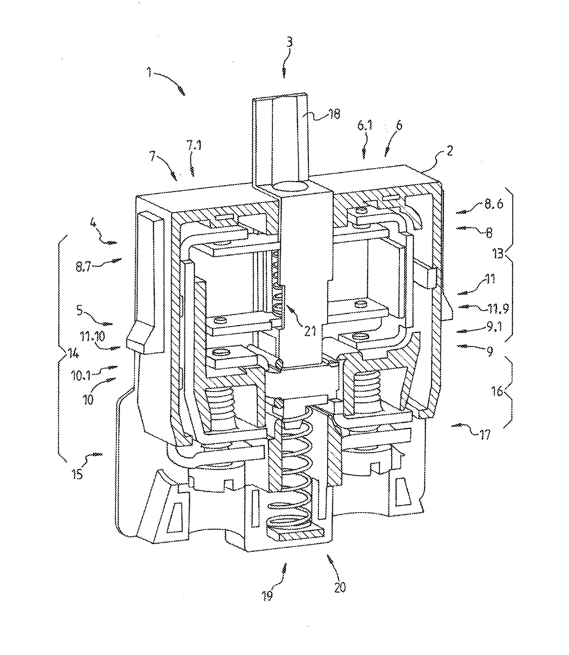
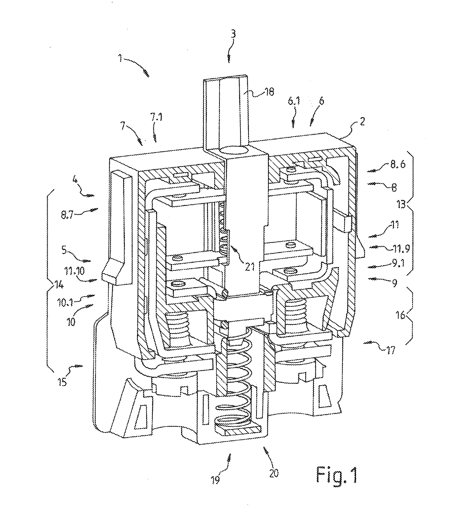
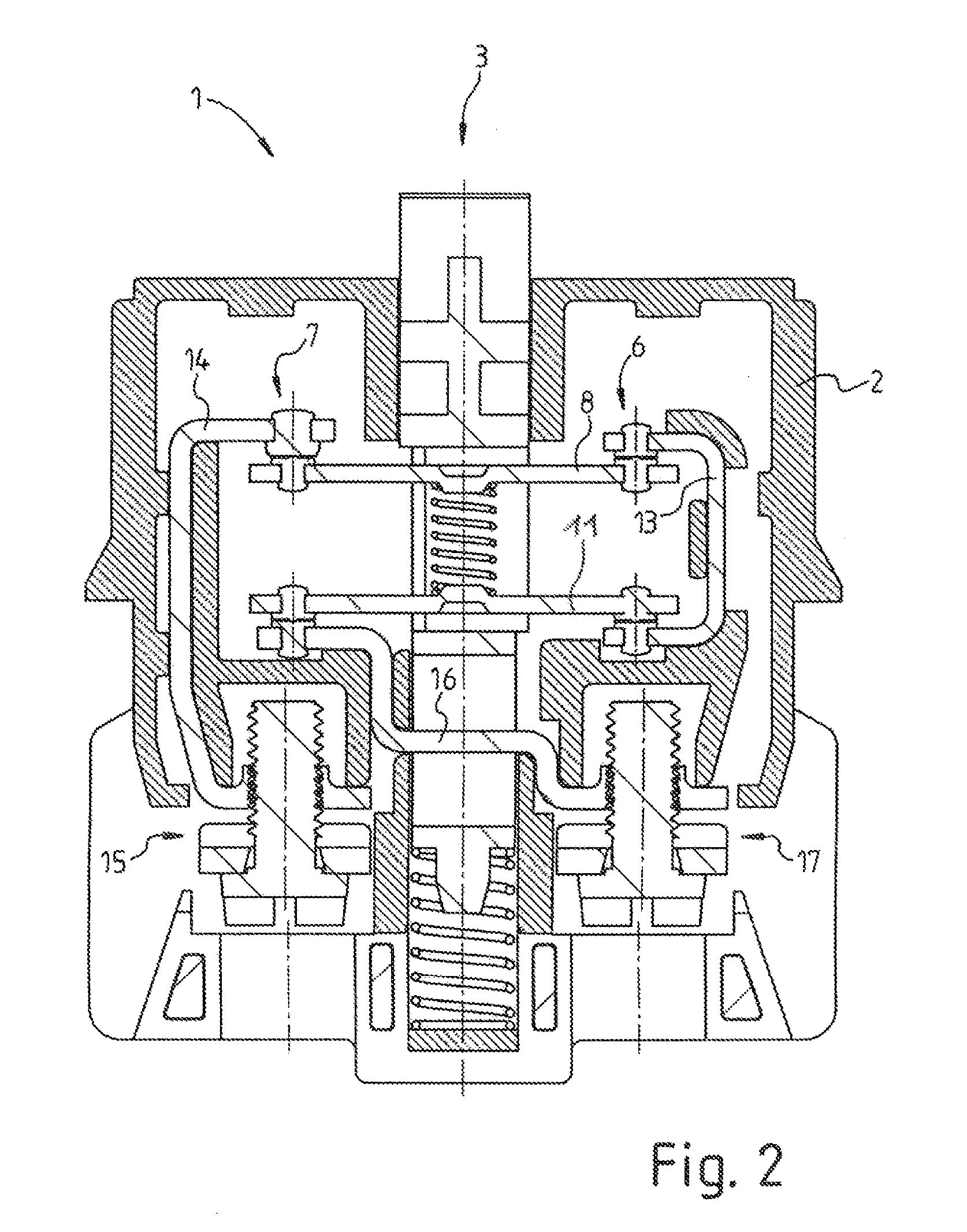
[0033]Accordingly, FIG. 1 shows an electrical contact device 1 with a housing 2 and a plunger 3 guided movably therein. The contact device 1 comprises a first and a second switching contact unit 4, 5, in each case for producing or isolating an electrically conductive connection depending on the plunger position along the axially provided positioning thereof corresponding to the switching positions prescribed for emergency-stop switches and illustrated in detail above. The first switching contact unit 4 comprises a first contact side 6, a second contact side 7 and a bridge element 8 connecting the respective contact points 6.1 and 7.1 of said contact sides. The bridge element can preferably also have contact points 8.6 and 8.7 consisting of a corresponding contact material. In the state illustrated, the closed switching contact unit 8 produces an electrically conductive connection.

[0034]Correspondingly, the second switching contact unit 5 comprises a first contact side 9 and a second...


PUM


Abstract

An electrical contact device including first and second switching contact units for producing or isolating electrically conductive connections, wherein a first contact side of the first switching contact unit is connected to a first contact side of the second switching contact unit, and a second contact side of the first switching contact unit is connected to a first connection contact of the contact device, and a second contact side of the second switching contact unit is connected to a second connection contact of the contact device, and wherein two switching contact units are designed to be actuable by a movable plunger acting on said switching contact units. The two connection contacts, in relation to the plunger, are arranged opposite one another on the contact device, and the first and second switching contact units are arranged within a mounting unit.

Description

CROSS REFERENCE TO RELATED APPLICATIONS[0001]This application is a continuation of International Application No. PCT / EP2011 / 004624 filed Sep. 15, 2011, which designated the United States, and claims the benefit under 35 USC §119(a)-(d) of German Application No. 10 2010 045 629.2 filed Sep. 17, 2010, the entireties of which are incorporated herein by reference.FIELD OF THE INVENTION[0002]The present invention relates to an electrical contact device and to a command device.BACKGROUND OF THE INVENTION[0003]For safety reasons, the provision of emergency-stop switches is prescribed for machines and electrical installations. Such emergency-stop switches, as are known, for example, from DE 4 101 493 C2, firstly comprise an electrical contact device and secondly comprise an actuation device provided for the actuation thereof. This two-part design is provided because the actuation device, which is often also referred to as an actuator, needs to be visible and accessible for reliable operatio...

Claims


Application Information

Patent Timeline
Patent Type & Authority Applications(United States)
IPC IPC(8): H01H3/02
CPCH01H3/022H01H1/2025H01H13/503
Inventor SCHLEGEL, EBERHARDBLANK, KURTDOLPP, RUDOLF
Owner GEORG SCHLEGEL GMBH & CO
Why Eureka
Try Eureka