Distributed antenna system for MIMO signals

a technology of distributed antennas and mimo signals, applied in the field of wireless communication systems, can solve the problems of siso systems, inability to increase spectral efficiency by taking advantage of spatial mimo technology, and significant increase in system capacity without extending bandwidth

Active Publication Date: 2013-08-01
COMMSCOPE TECH LLC
View PDF38 Cites 171 Cited by
  • Summary
  • Abstract
  • Description
  • Claims
  • Application Information

AI Technical Summary

Problems solved by technology

This may lead to a significant increase in the system capacity without extending the bandwidth requirements.
Generally, a SISO system, such as that illustrated in FIG. 1, cannot increase spectral efficiency by taking advantage of spatial MIMO technology.
The wireless signals 24 from each remote unit are typically at the same frequency and carry the same data, and communication between a plurality of remote units 12 and the wireless device 26 simultaneously may result in signal degradation and collisions.

Method used


Image

  • Distributed antenna system for MIMO signals
  • Distributed antenna system for MIMO signals
  • Distributed antenna system for MIMO signals

Examples


Embodiment Construction

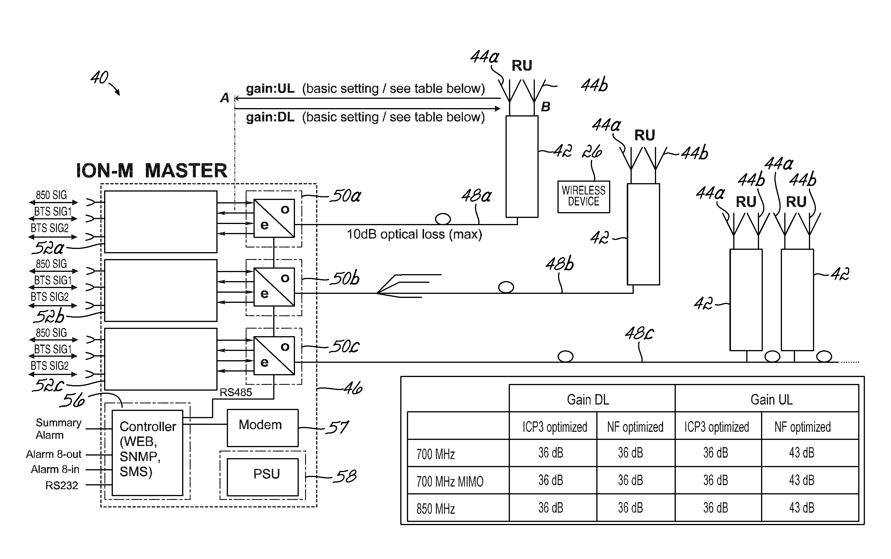
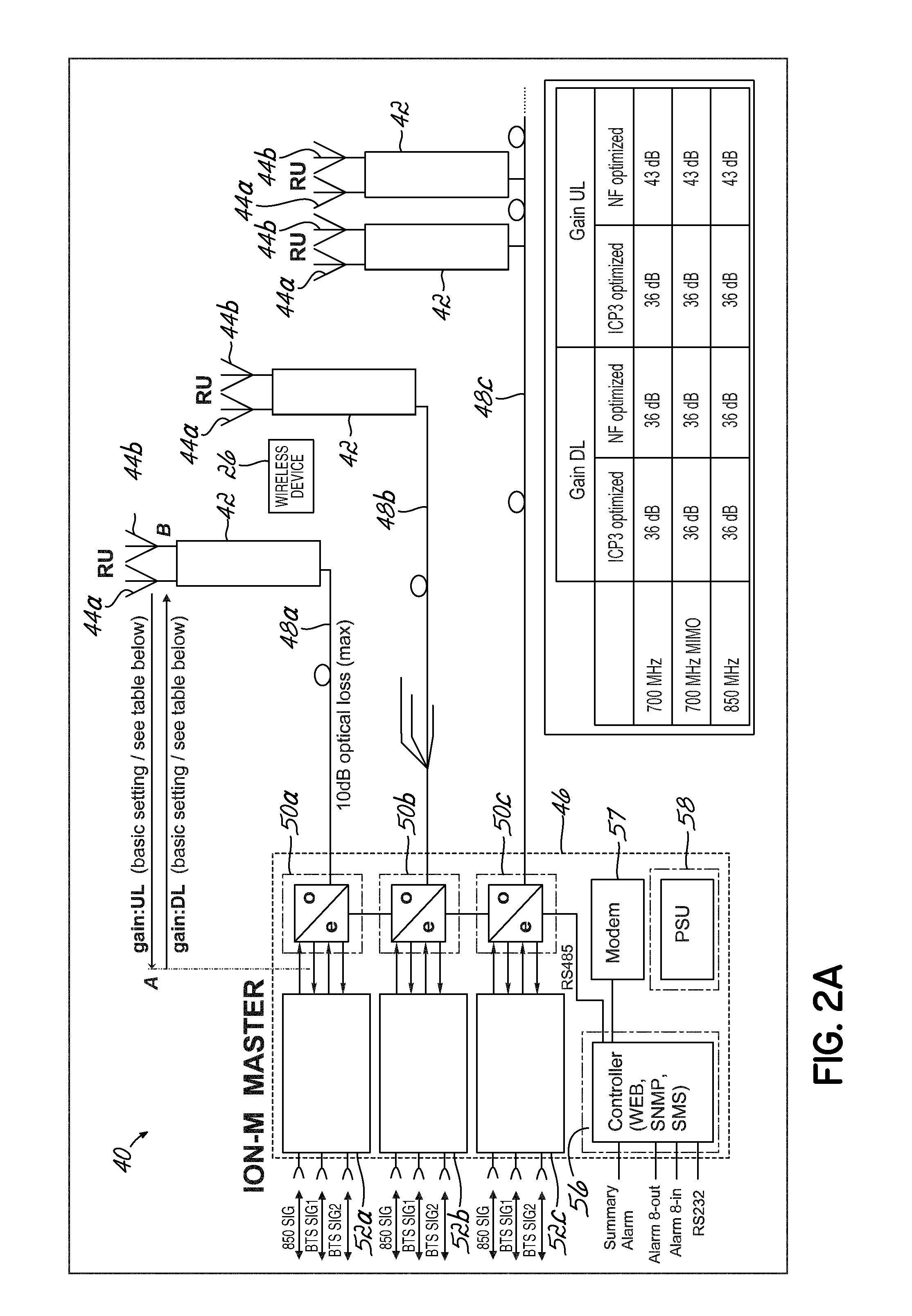
[0032]FIG. 2A is a diagrammatic illustration of a MIMO DAS 40 consistent with embodiments of the invention that further shows downlink (“DL”) and uplink (“UL”) gain of that MIMO DAS 40. The MIMO DAS 40 includes a plurality of remote units 42 distributed to provide coverage within a service area of the MIMO DAS 40, such as inside a building or some other enclosed area. Each remote unit 42, in turn, includes at least two antennas 44a-b and suitable electronics. In various of the disclosed embodiments, a 2×2 MIMO arrangement is illustrated or discussed. It should be understood that other MIMO scenarios, such as 4×4 or 8×8, etc., would also benefit from the invention. Each remote unit 42 is coupled to a master unit 46 through at least one optical link 48, which may include one or more optical fibers (not shown), optical splitters (not shown), or other optical transmission components (not shown). As illustrated in FIG. 2A, one remote unit 42 may be connected directly to the master unit 4...


PUM


Abstract

A distributed antenna system includes a master unit configured to receive at least one set of multiple input multiple output (MIMO) channel signals from at least one signal source. The master unit is configured to frequency convert at least one of the MIMO channel signals to a different frequency from an original frequency, and combine the MIMO channel signals for transmission. An optical link couples the master unit with a remote for transceiving the MIMO channel signals. The remote unit is configured to receive the MIMO channel signals to be transmitted over antennas and includes an extension port configured to transceive at least one of the MIMO channel signals. An extension unit is coupled to the remote unit and is configured to frequency convert at least one of the first and second MIMO channel signals from the different frequency back to an original frequency for transmission over an antenna.

Description

CROSS-REFERENCE TO RELATED APPLICATIONS[0001]This application is a continuation of International PCT Application No. PCT / US2011 / 054281, filed Sep. 30, 2011, entitled “DISTRIBUTED ANTENNA SYSTEM FOR MIMO SIGNALS”, which claims priority to and the filing benefit of U.S. Provisional Patent Application Ser. No. 61 / 388,973 filed on Oct. 1, 2010 and entitled “DISTRIBUTED ANTENNA SYSTEM FOR MIMO SIGNALS”, which applications are incorporated by reference herein in their entireties.FIELD OF THE INVENTION[0002]Embodiments of the invention are directed to wireless communication systems, and specifically directed to distributed antenna systems for wireless MIMO communications.BACKGROUND OF THE INVENTION[0003]A contemporary wireless communication system for repeating wireless signals, such as distributed antenna system 10, is shown in FIG. 1, and includes a number of remote units 12 distributed to provide coverage within a service area of the system 10. In particular, each remote antenna unit 12...

Claims


Application Information

Patent Timeline
Patent Type & Authority Applications(United States)
IPC IPC(8): H04B7/04
CPCH04B7/0413H04B10/25753H04B1/0096
Inventor SCHMID, PETERGUNZNER, PETERLANGER, HARALDEISENWINTER, STEFANBRAZ, OLIVERFABBRI, MARIANNAFABBRI, ENRICO MARIABRIGHENTI, SAMUELEPARRUCCI, MARCOMINI, MASSIMILIANOKUMMETZ, THOMAS
Owner COMMSCOPE TECH LLC
Why Eureka
Try Eureka