Fixing device and image forming apparatus

a technology of fixing device and image forming apparatus, which is applied in the direction of electrographic process apparatus, instruments, optics, etc., can solve the problems of fixing failure, large temperature drop, and possible failure of fixing devi

Active Publication Date: 2013-08-01
RICOH KK
View PDF12 Cites 17 Cited by
  • Summary
  • Abstract
  • Description
  • Claims
  • Application Information

AI Technical Summary

Problems solved by technology

In a fixing device, fixing failure may occur due to the following reasons.
However, when the necessary quantity of heat is not secured at the start of continuous printing, a large drop in temperature occurs, and when a sheet passes through while the necessary quantity of heat is not reached in speed-up continuous printing, fixing failure may result.
This may lead to what is known as temperature drop in which the quantity of heat is insufficient particularly at the start of continuous printing, and may lead to fixing failure when sped up.
In the SURF fixing method, compared with a belt-type fixing device, lowering of heat capacity and downsizing is possible, whereby a time for rising to a given temperature and the first print time can be shortened but there are following problems.
That is, in the SURF fixing method, because the portion other than the local portion are not heated, the belt is in a coldest state at the entrance of a nip for a sheet or the like, whereby fixing failure is likely to occur.
Particularly, a high-speed device has the problem that fixing failure is more likely to occur because the rotation of the belt is fast and thus the heat dissipation of the belt at the portion other than the nip portion becomes large.
As a result, if a sufficient strength of the nip forming member 500 cannot be achieved and the deflection of the nip forming member 500 is caused by the applied pressure of the pressing roller 400, unevenness occurs in the distribution of contact pressure or the width of the nip in the nip portion N, whereby fixing failure may occur.

Method used


Image

  • Fixing device and image forming apparatus
  • Fixing device and image forming apparatus
  • Fixing device and image forming apparatus

Examples


Embodiment Construction

[0047]An embodiment of the present invention will be described hereinafter with reference to the accompanying drawings.

[0048]In the respective drawings for explaining the embodiments of the present invention, constituent elements such as members and components having the same function or shape are provided with the same reference numerals or symbols as long as they are recognizable, and once they are explained, redundant explanations are omitted.

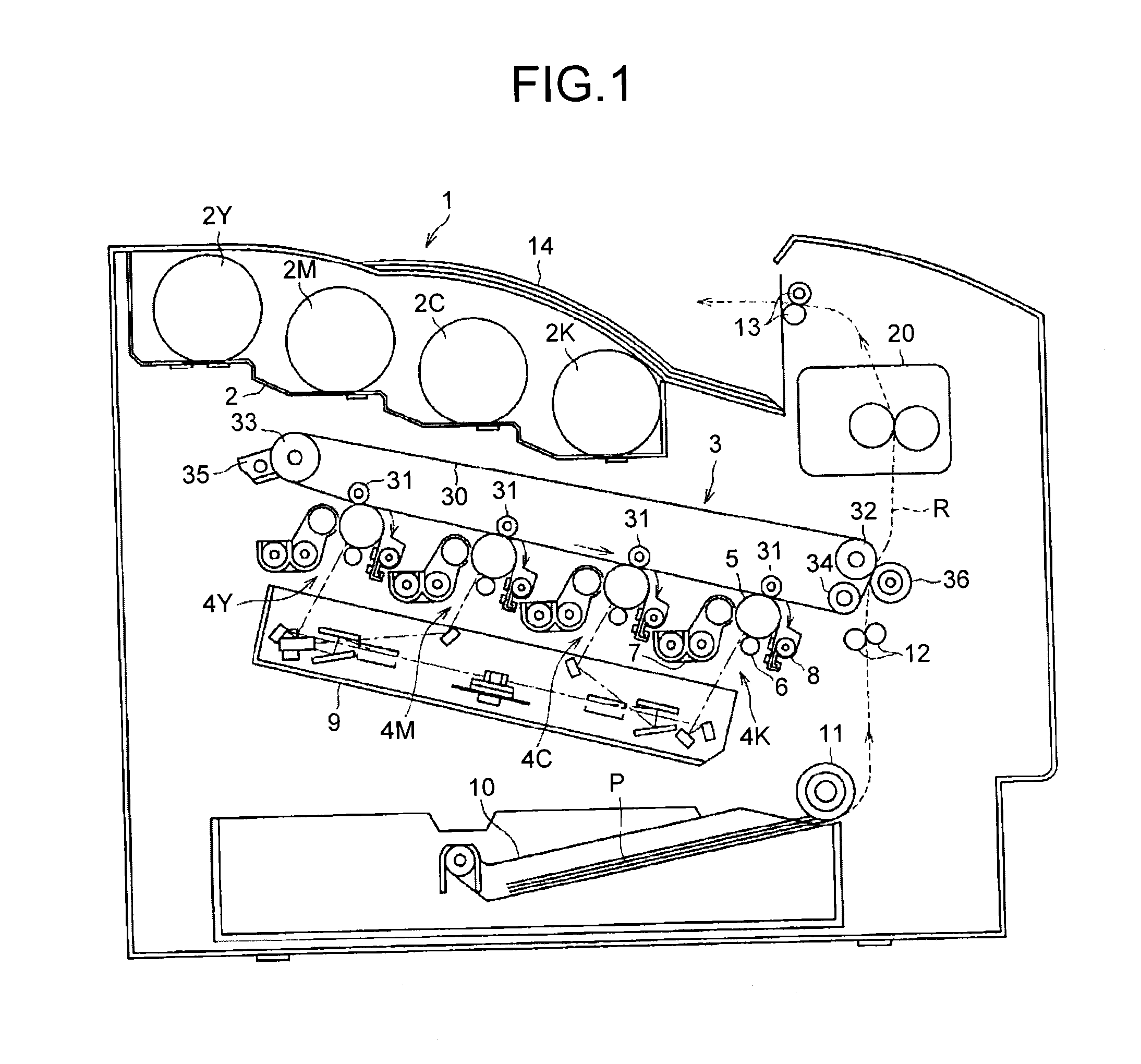
[0049]With reference to FIG. 1, an overall configuration and operation of an image forming apparatus according to an embodiment of the present invention will be described first.

[0050]An image forming apparatus 1 illustrated in FIG. 1 is a color laser printer, and in the middle of a main body of the apparatus, four image forming units 4Y, 4M, 4C, and 4K are provided. The image forming units 4Y, 4M, 4C, and 4K have the same configuration except for that they house developer of different colors of yellow (Y), magenta (M), cyan (C), and black (K...


PUM


Abstract

A fixing device includes: a rotatable endless fixing belt; a nip forming member arranged inside the fixing belt; a facing rotating body that abuts the nip forming member via the fixing belt to form a nip portion with the fixing belt; a heat source that directly heats up the fixing belt at a portion other than the nip portion; and a supporting member that supports the nip forming member. The fixing device conveys a recording medium carrying an unfixed image to the nip portion to fix the unfixed image to the recording medium, and the supporting member includes a rising portion extending in an abutting direction of the facing rotating body against the fixing belt and having a tip close to an inner circumferential surface of the fixing belt, and is set to have a section modulus of 200 mm3 or higher.

Description

CROSS-REFERENCE TO RELATED APPLICATIONS[0001]The present application claims priority to and incorporates by reference the entire contents of Japanese Patent Application No. 2012-017929 filed in Japan on Jan. 31, 2012 and Japanese Patent Application No. 2012-216290 filed in Japan on Sep. 28, 2012.BACKGROUND OF THE INVENTION[0002]1. Field of the Invention[0003]The present invention relates to a fixing device and an image forming apparatus, and more particularly, to a belt fixing mechanism that uses a belt as a fixing member.[0004]2. Description of the Related Art[0005]As is well known, an electrophotographic image forming apparatus outputs a copy image by the following processes.[0006]That is, a latent image formed on a photosensitive element that is a latent image carrier is processed to be visualized by toner, and the toner image is transferred onto a recording medium such as a recording sheet and then fixed to the recording medium, whereby the copy image is output.[0007]A fixing me...

Claims


Application Information

Patent Timeline
Patent Type & Authority Applications(United States)
IPC IPC(8): G03G15/20
CPCG03G15/2053G03G15/2064G03G2215/2035
Inventor YOSHINAGA, HIROSHISATOH, MASAHIKOYOSHIKAWA, MASAAKIISHII, KENJIOGAWA, TADASHITAKAGI, HIROMASAIWAYA, NAOKISESHITA, TAKUYAIMADA, TAKAHIROGOTOH, HAJIMESUZUKI, AKIRAKAWATA, TEPPEISHIMOKAWA, TOSHIHIKOYOSHIURA, ARINOBUHASE, TAKAMASAUCHITANI, TAKESHIYUASA, SHUUTAROHYAMAJI, KENSUKE
Owner RICOH KK
Why Eureka
Try Eureka