
Indwelling device delivery system

a technology of indwelling devices and delivery systems, which is applied in the field of indwelling device delivery systems, can solve the problems of weakening the retention force of the stent, and difficult to maintain the bonding effect by chemical interaction in the long term

Inactive Publication Date: 2013-08-01
TERUMO KK
View PDF3 Cites 5 Cited by
  • Summary
  • Abstract
  • Description
  • Claims
  • Application Information

AI Technical Summary

Benefits of technology

[0007]The present invention is made in order to solve the abovementioned problem associated with the related art, and to provide an indwelling device delivery system that does not

Problems solved by technology

However, it causes a problem of making pinholes in the balloon thus during the crimping process and also a problem of weakening the retention force of the stent when it passes through a bending part of a lumen in human body.
On the other hand, if the balloon and the stent are secured together by a c

Method used


Image

  • Indwelling device delivery system
  • Indwelling device delivery system
  • Indwelling device delivery system

Examples


Embodiment Construction

[0037]The embodiment of this invention will be described below with reference to the drawings.

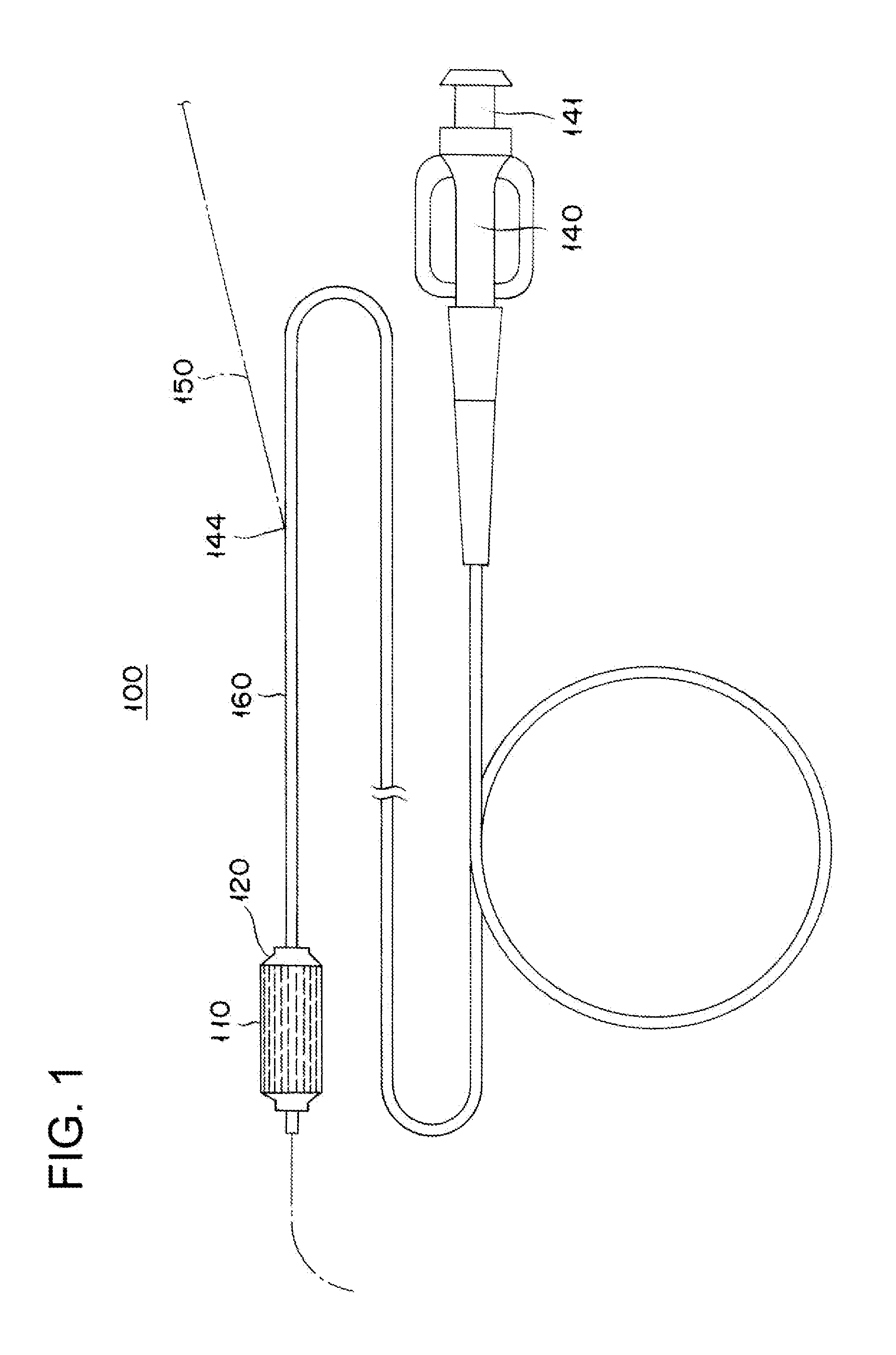
[0038]FIG. 1 is a schematic view of assistance in explaining a stent delivery system according to an embodiment of the present invention.

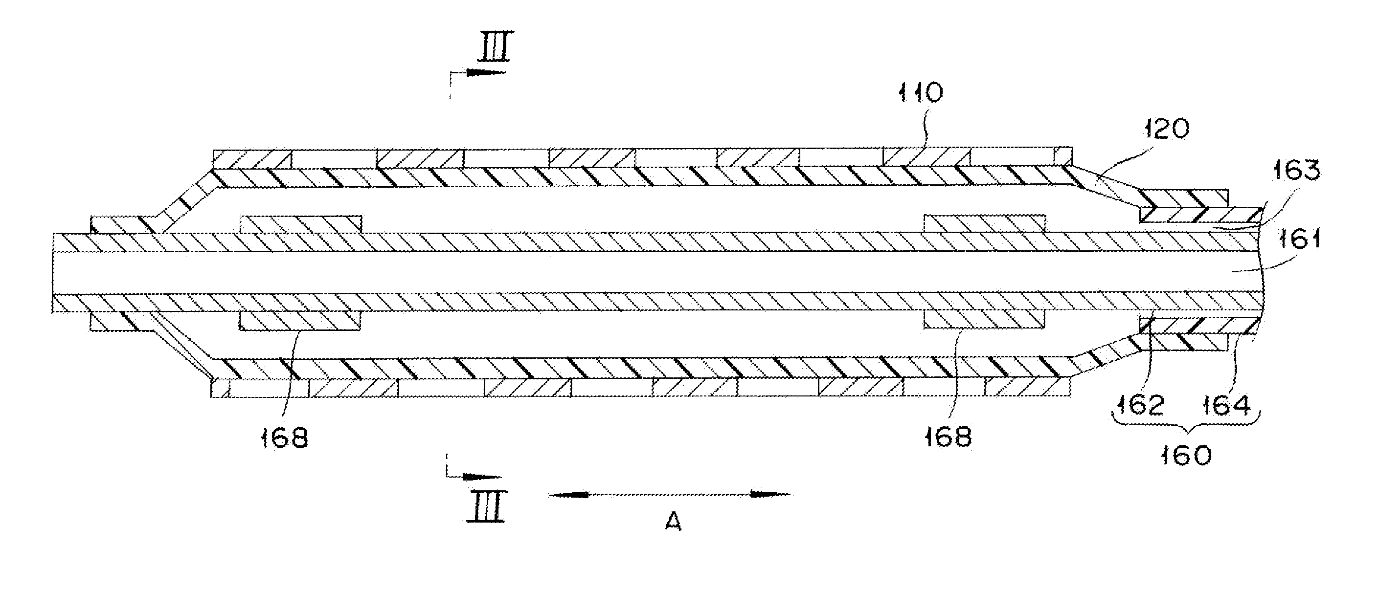
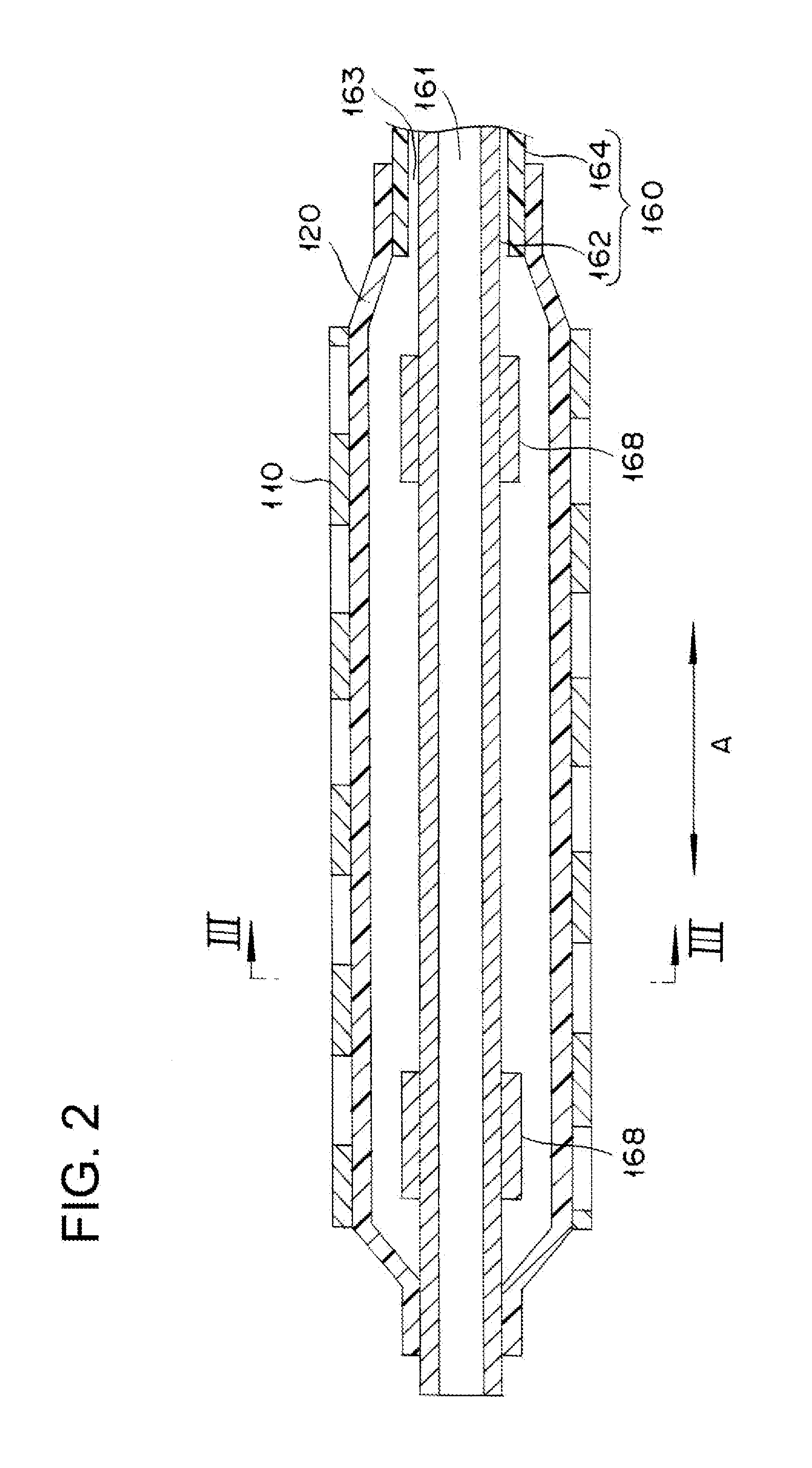
[0039]A stent delivery system 100 according to an embodiment of the present invention is of a rapid exchange type with a guide wire 150 passing only through the distal part, is used for improving a narrowed area (or an obstructed area) developed in a lumen in human body, and has a hollow shaft tube 160, a balloon 120 mounted on the circumference of the distal part of the shaft tube 160, a stent 110 mounted on the circumference of the balloon 120, and a hub 140 located at the proximal part of the shaft tube 160 as shown in FIG. 1. Moreover, a guide wire port 144 is provided in the middle of the shaft tube 160. The guide wire port 144 is used for guiding the guide wire 150 through the shaft tube 160 to be projected from the distal part.

[0040]A typical lumen ...


PUM


Abstract

An indwelling device delivery system including a hollow shaft, a dilatable balloon mounted on a circumference of a distal part of the shaft, and an indwelling device mounted on a circumference of the balloon and expanded by dilatation of the balloon. The balloon has a plurality of protrusions for adhering to the indwelling device and the protrusions are constructed so as to elicit adhesion force based on physical adhesion due to van der Waals force by means of creating more surface area.

Description

CROSS-REFERENCE TO RELATED APPLICATION[0001]This application is based on U.S. Provisional Application No. 61 / 592,821 filed on Jan. 31, 2012, the contents of which are incorporated herein by reference.BACKGROUND[0002]1. Technical Field The present invention relates to an indwelling device delivery system.[0003]2. Description of the Related Art[0004]A stent is an indwelling device used for improving a narrowed area or an obstructed area generated in a lumen in human body. A stent delivery system has a dilatable balloon that is mounted on the circumference of a distal part of a hollow shaft, and a stent mounted on the outside of the balloon so that the stent can be expanded by the balloon as it expands.[0005]The balloon has protrusions that are engaged with the stent in such a way that any displacement of the stent relative to the balloon and the dislodgement (separation) of the stent and the balloon can be restrained. The protrusions of the balloon are formed by causing a portion of t...

Claims


Application Information

Patent Timeline
IPC IPC(8): A61F2/958
CPCB05B13/0442B05C5/0212B05C11/10A61F2/958A61M2025/1088A61M25/1029A61M2025/1031A61M2025/1086A61F2002/9583
Inventor ISHII, NAOKI
Owner TERUMO KK
Learn More