
Programmable irrigation controller having user interface

a programmable irrigation controller and user interface technology, applied in the field of user interfaces of programmable irrigation controllers, can solve the problems of difficult to establish irrigation schedules using program-based irrigation controllers, user interfaces that do not show all parameters associated, and it is difficult for users of conventional program-based irrigation controllers to get a complete picture of any particular irrigation schedul

Active Publication Date: 2013-08-01
RAIN BIRD CORP
View PDF6 Cites 8 Cited by
  • Summary
  • Abstract
  • Description
  • Claims
  • Application Information

AI Technical Summary

Benefits of technology

The patent describes an irrigation controller with a user interface that allows users to create and view irrigation schedules. The controller includes a microcontroller that stores and executes the irrigation schedule, a valve driver that controls the activation of valves, and a user interface that includes a plurality of user input devices and a display that shows information about the irrigation schedule. The user interface also allows users to view and interact with the system variables that affect the irrigation schedule. The technical effects of this patent include improved user experience, flexibility, and efficient water usage.

Problems solved by technology

Because users often intuitively think in terms of irrigation events that will occur within a particular zone, rather than in terms of abstract programs that are assigned to zones, irrigation schedules can be difficult to establish using program-based irrigation controllers.
Such user interfaces, however, typically do not show all parameters associated with an irrigation schedule at one time.
As a result, it can be difficult for users of conventional program-based irrigation controllers to get a complete picture of any particular irrigation schedule.
Thus, for many users, the user interface can be confusing and difficult to understand.

Method used


Image

  • Programmable irrigation controller having user interface
  • Programmable irrigation controller having user interface
  • Programmable irrigation controller having user interface

Examples


Embodiment Construction

[0035]The following description is not to be taken in a limiting sense, but is made merely for the purpose of describing the general principles of exemplary embodiments described herein. The scope of the invention should be determined with reference to the claims.

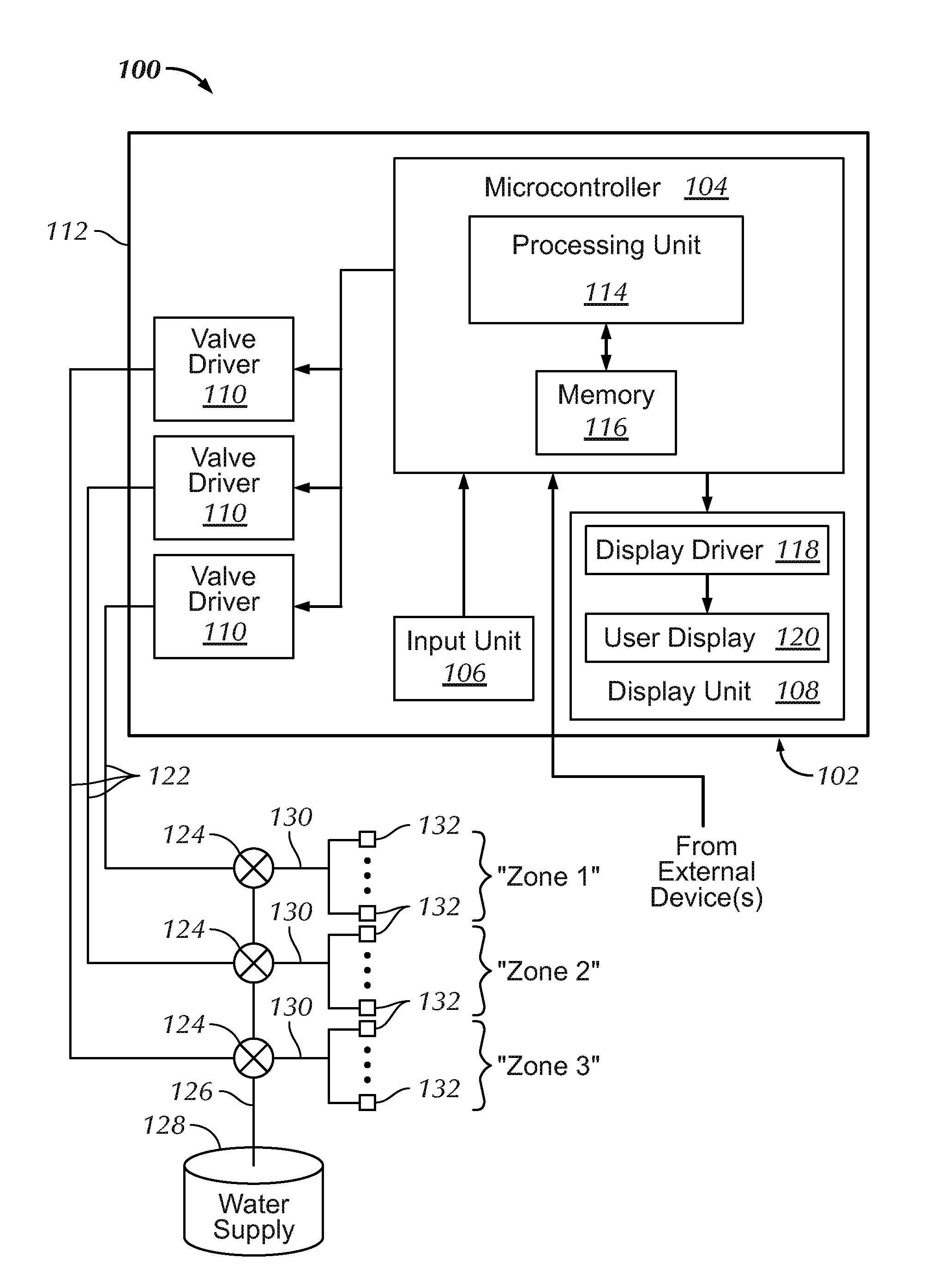
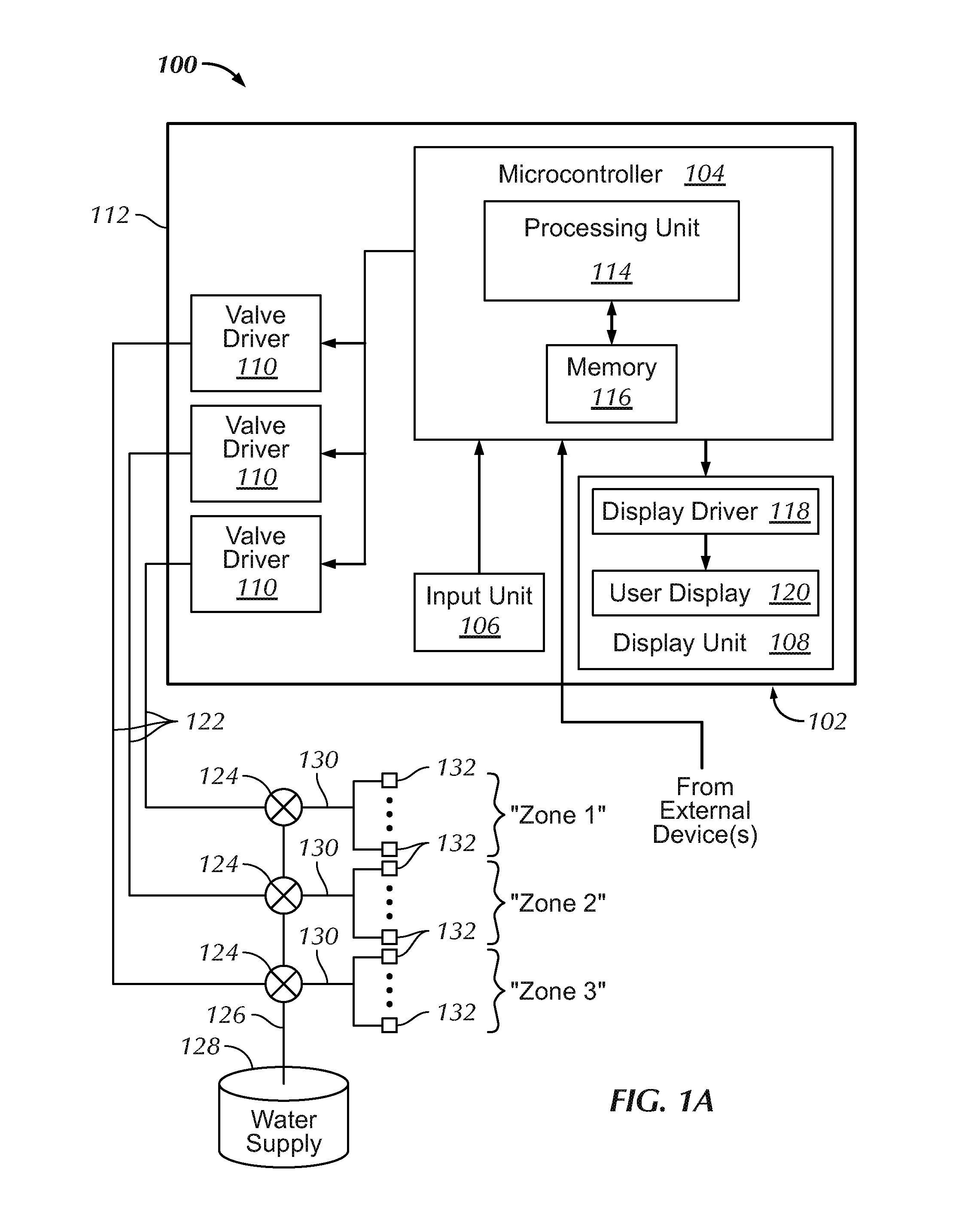
[0036]Referring first to FIG. 1A, an exemplary irrigation system 100 is shown as including a zone-based programmable irrigation controller 102 (also referred to simply as an “irrigation controller”), a microcontroller 104, an input unit 106, a display unit 108, a plurality of valve drivers 110, a housing 112, a processing unit 114, a memory 116, a display driver 118, a user display 120, a plurality of actuation lines 122, a plurality of zone valves 124, a main irrigation line 126, a water supply 128, a plurality of branch irrigation lines 130, and a plurality of irrigation devices 132.

[0037]As generally illustrated, the irrigation controller 102 is typically provided as a specific purpose computing device located within an ...


PUM


Abstract

An irrigation controller, includes a housing, a microcontroller within the housing and configured to store and execute an irrigation schedule, a valve driver coupled to the microcontroller and configured to output a zone activation signal to an actuatable zone valve in response to signaling from the microcontroller, and a user interface. The user interface includes a plurality of user input devices coupled to the microcontroller and configured to provide signaling to the microcontroller based upon a user's engagement therewith, the plurality of user input devices configured to allow the user to create an irrigation schedule; and a user display coupled to the microcontroller and configured to display irrigation parameters associated with the irrigation schedule. The microcontroller is configured to cause the user display to display at least one of a next irrigation start day, a next irrigation start time, and a next zone to irrigate associated with the irrigation schedule.

Description

[0001]This application is a continuation of U.S. application Ser. No. 11 / 424,504, filed Jun. 15, 2006 which claims the benefit of U.S. Provisional Application No. 60 / 691,616, filed Jun. 17, 2005, both of which are incorporated in their entirety herein by reference.BACKGROUND[0002]1. Field of Invention[0003]Embodiments exemplarily described herein relate generally to user interfaces of programmable irrigation controllers and methods of presenting information to users of irrigation controllers.[0004]2. Discussion of the Related Art[0005]Generally, programmable irrigation controllers are used to control the delivery of water to irrigation devices connected to switchable irrigation valves. To control the delivery of water to groups of irrigation devices that define irrigation stations or zones, users (e.g., residential users) of conventional program-based irrigation controllers typically create programs that define different watering days and start times for each watering day. Once a pr...

Claims


Application Information

Patent Timeline
Patent Type & Authority Applications(United States)
IPC IPC(8): A01G25/16
CPCA01G25/16A01G25/165
Inventor WEILER, STEVEN W.BASCH, SUSAN E.LEATHERMAN, RUSSEL DEANMUSSELMAN, JAMES R.
Owner RAIN BIRD CORP
Learn More