Skylight energy management system

a management system and energy management technology, applied in the field of radiant energy management, can solve the problems of inability to transmit heat far without substantial parasitic losses, the capital cost of hot water and other heat transmission systems, and the challenge of most existing or previous concentrator methods

Inactive Publication Date: 2013-08-08
MBC VENTURES INC
View PDF9 Cites 8 Cited by
  • Summary
  • Abstract
  • Description
  • Claims
  • Application Information

AI Technical Summary

Benefits of technology

[0006]Disclosed is a system and method for harvesting solar energy, and more particularly an energy-positive skylighting system that may provide an integrated energy solution to a variety of commercial buildings. A plurality of skylight modules are provided, each having a plurality of louvers configured to reflect incoming sunlight onto a thermal receiver area on an adjacent louver to heat a working fluid in communication with the louvers (i.e., such that heat transfer is carried out between the thermal receiver and the working fluid), all while allowing control of the amount of daylight that passes through the module. The modules are constructed such that the balance of the solar energy not going into daylighting is captured in the form of thermal heat, which in turn may be applied to building system cooling and heating applications.

Problems solved by technology

Unfortunately, however, “solar cogeneration” systems need to be located at the site of use, which presents challenges to most existing or previous concentrator methods.
), the heat energy cannot be transmitted far without substantial parasitic losses.
Further, the capital cost of hot water and other heat transmission systems favors direct on-site use.
And, such low temperature heat generally cannot be converted in a heat engine to mechanical or electrical power because of the small temperature differential versus ambient temperatures.
Solar cogeneration technologies are, in part, held back by challenges in creating optical systems that are both inexpensive and that can be mounted or integrated into a building.
One problem is the practical limit for how tall a design can be to withstand forces from windy conditions on the device and building on which it may be mounted.
Tying a cogeneration apparatus into the foundation or load bearing structure of a building creates expensive installations and / or mounting systems to accommodate system stresses, particularly on the roof.
Many commercial sites lack sufficient ground space for a reasonably sized system, and roof-mounting is the only viable option to obtain sufficient collector area.

Method used


Image

  • Skylight energy management system
  • Skylight energy management system
  • Skylight energy management system

Examples


Embodiment Construction

[0026]The following description is of a particular embodiment of the invention, set out to enable one to practice an implementation of the invention, and is not intended to limit the preferred embodiment, but to serve as a particular example thereof. Those skilled in the art should appreciate that they may readily use the conception and specific embodiments disclosed as a basis for modifying or designing other methods and systems for carrying out the same purposes of the present invention. Those skilled in the art should also realize that such equivalent assemblies do not depart from the spirit and scope of the invention in its broadest form.

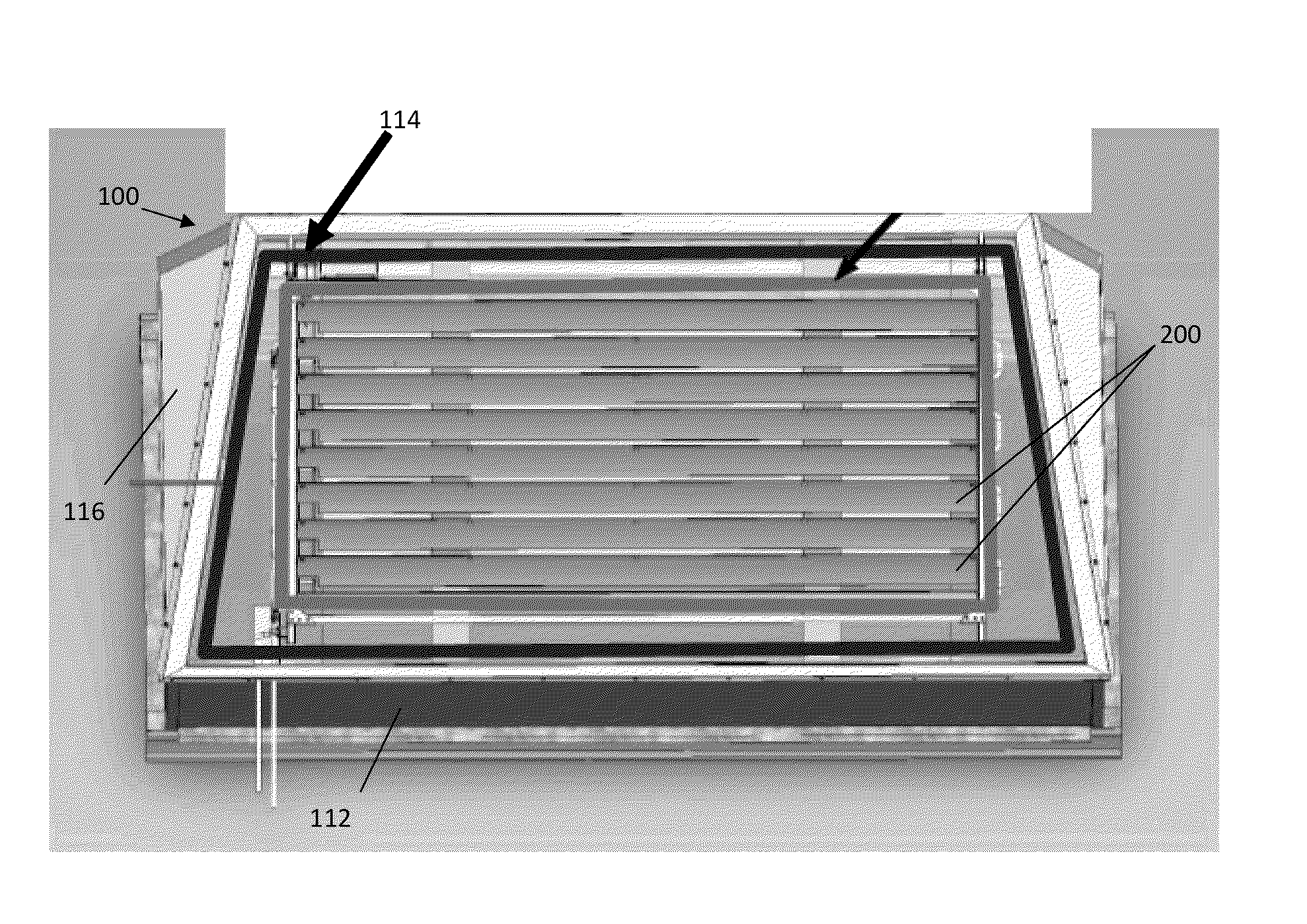
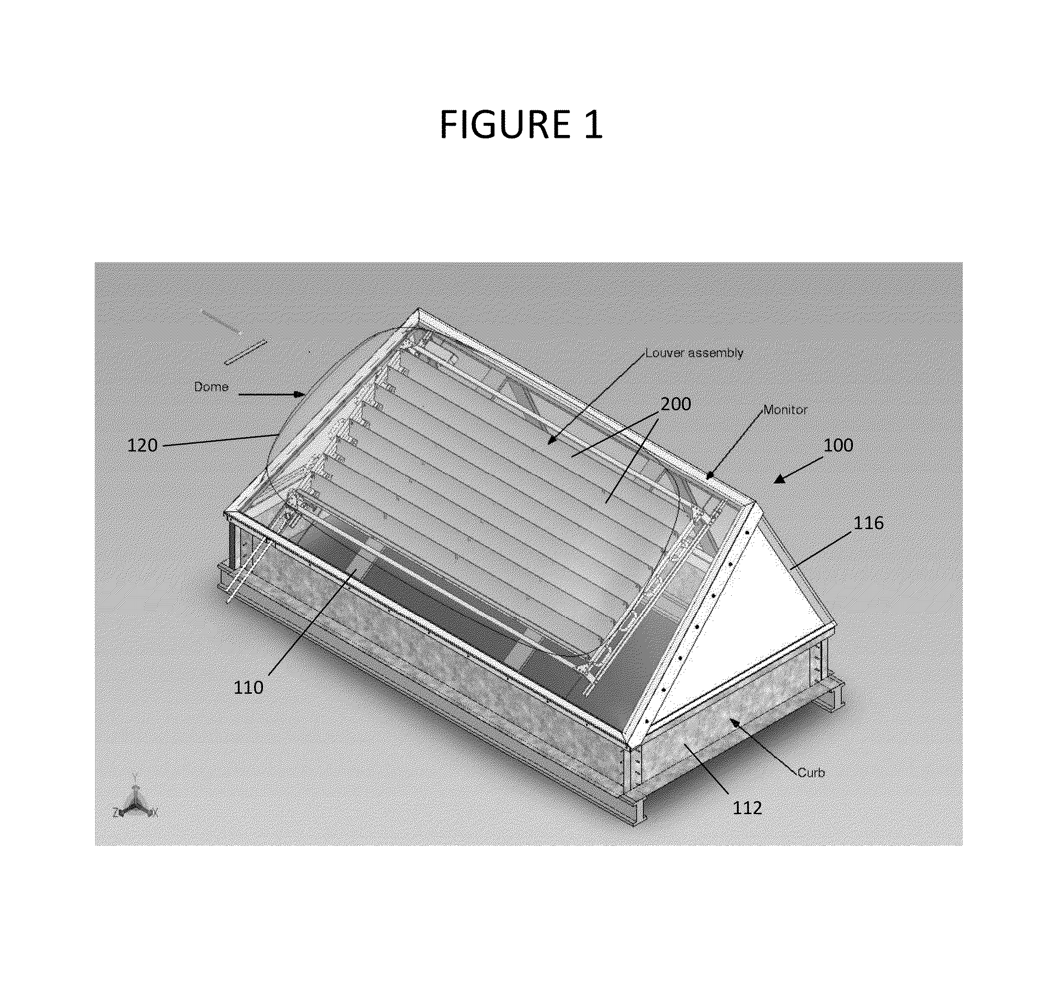
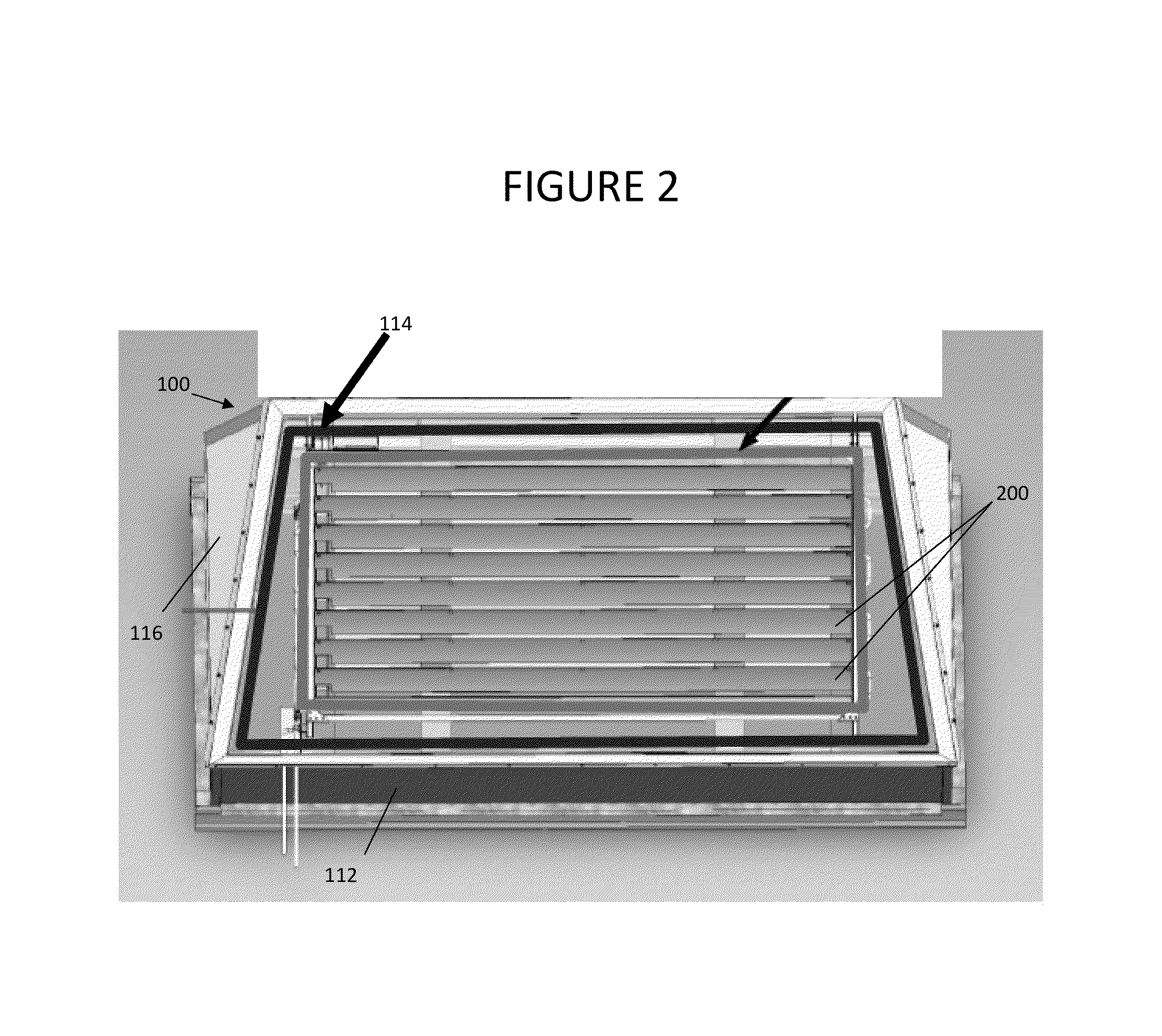
[0027]FIG. 1 shows a perspective view of a skylight module (shown generally at 100) in accordance with certain aspects of an embodiment of the invention, the module being configured for installation in, for instance, the roof of a building, such as a commercial building. The module is configured to provide approximately 50-70 percent more daylig...


PUM


Abstract

Disclosed is a system and method for harvesting solar energy, and more particularly an energy-positive sky lighting system that may provide an integrated energy solution to a variety of commercial buildings. A plurality of skylight modules are provided, each having a plurality of louvers configured to reflect incoming sunlight onto a thermal receiver area on an adjacent louver to heat a working fluid in communication with the louvers (i.e., such that heat transfer is carried out between the thermal receiver and the working fluid), all while allowing control of the amount of daylight that passes through the module. The modules are constructed such that the balance of the solar energy not going into day lighting is captured in the form of thermal heat, which in turn may be applied to building system cooling and heating applications.

Description

CROSS REFERENCE TO RELATED APPLICATION[0001]This application is based upon and claims benefit of copending U.S. Provisional Patent Application Ser. No. 61 / 589,933 entitled “Skylight Energy Management System,” filed with the U.S. Patent and Trademark Office on Jan. 24, 2012 by the inventor herein, the specification of which is incorporated herein by reference.FIELD OF THE INVENTION[0002]This invention relates to radiant energy management, and more particularly to systems for capturing solar energy to manage illumination and temperature within a defined space.BACKGROUND OF THE INVENTION[0003]Solar generation and cogeneration systems can offer a logical alternative or addition to fossil fueled energy systems as fuel costs and environmental concerns increase. The solar heat that is collected in a collection system, with or without electricity (such as by way of photovoltaic cells), may provide a major boost to an energy system's value. Unfortunately, however, “solar cogeneration” system...

Claims


Application Information

Patent Timeline
Patent Type & Authority Applications(United States)
IPC IPC(8): F24J2/04E06B9/02F24J2/46E04D13/035F24J2/34F24S23/74
CPCE06B7/086Y02E60/142E04D13/0351F24J2/345F24J2/46E06B9/02F24J2/10F24J2/268F24J2/541F28D20/0039F24J2002/0411F24J2002/1014F28D2020/0086F24J2002/4601Y02B10/20Y02E10/44Y02E70/30F24J2/0433F24S20/63F24S23/70F24S10/755F24S30/425F24S2020/183F24S2023/832F24S2080/03Y02E60/14E04D13/035
Inventor TANDLER, JOHN JOSEPH
Owner MBC VENTURES INC
Why Eureka
Try Eureka