Rotary hammer

Active Publication Date: 2013-08-08
MILWAUKEE ELECTRIC TOOL CORP
View PDF3 Cites 27 Cited by
  • Summary
  • Abstract
  • Description
  • Claims
  • Application Information

AI Technical Summary

Problems solved by technology

This reciprocation may cause undesirable vibrations t

Method used


Image

  • Rotary hammer
  • Rotary hammer
  • Rotary hammer

Examples


Embodiment Construction

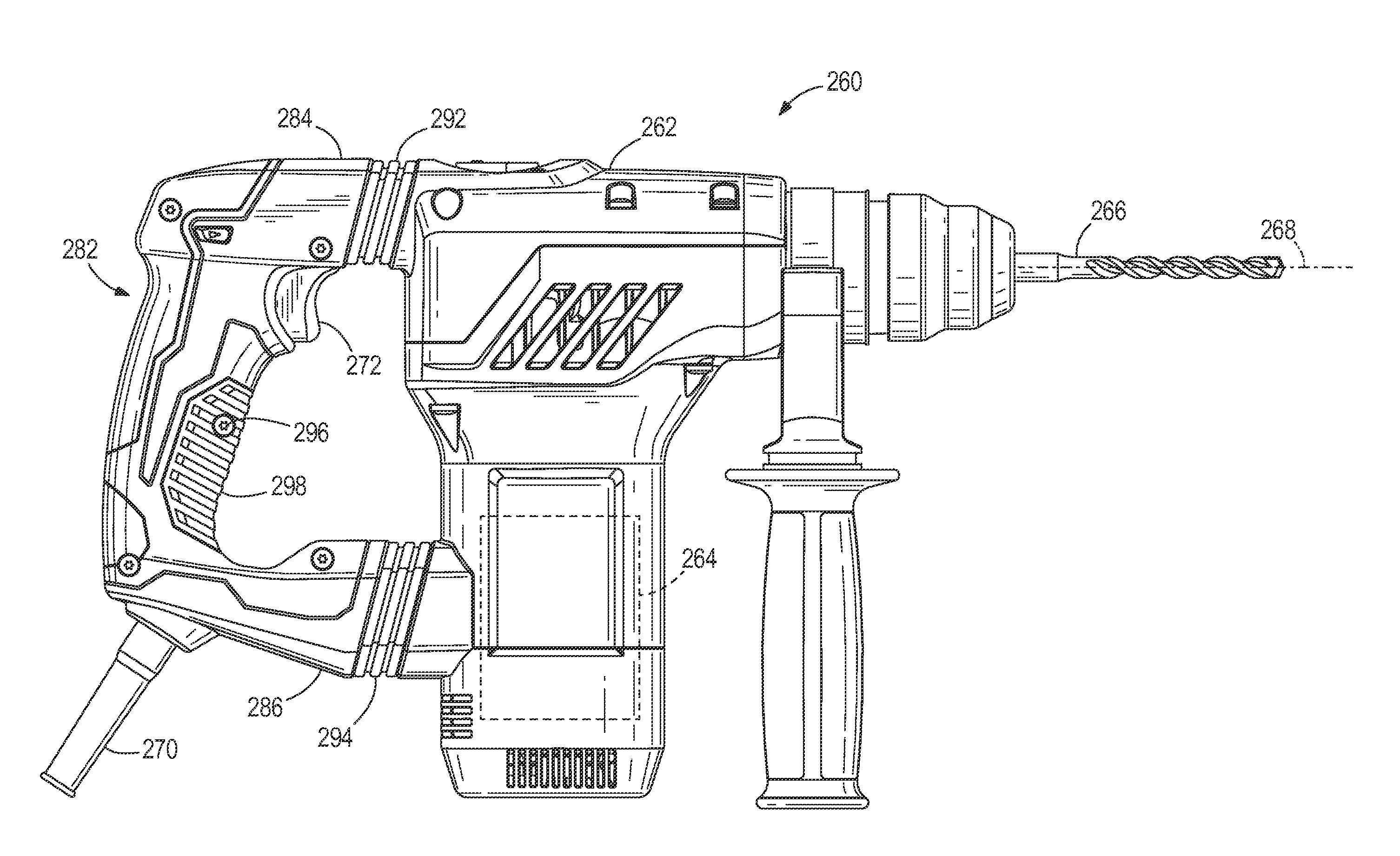
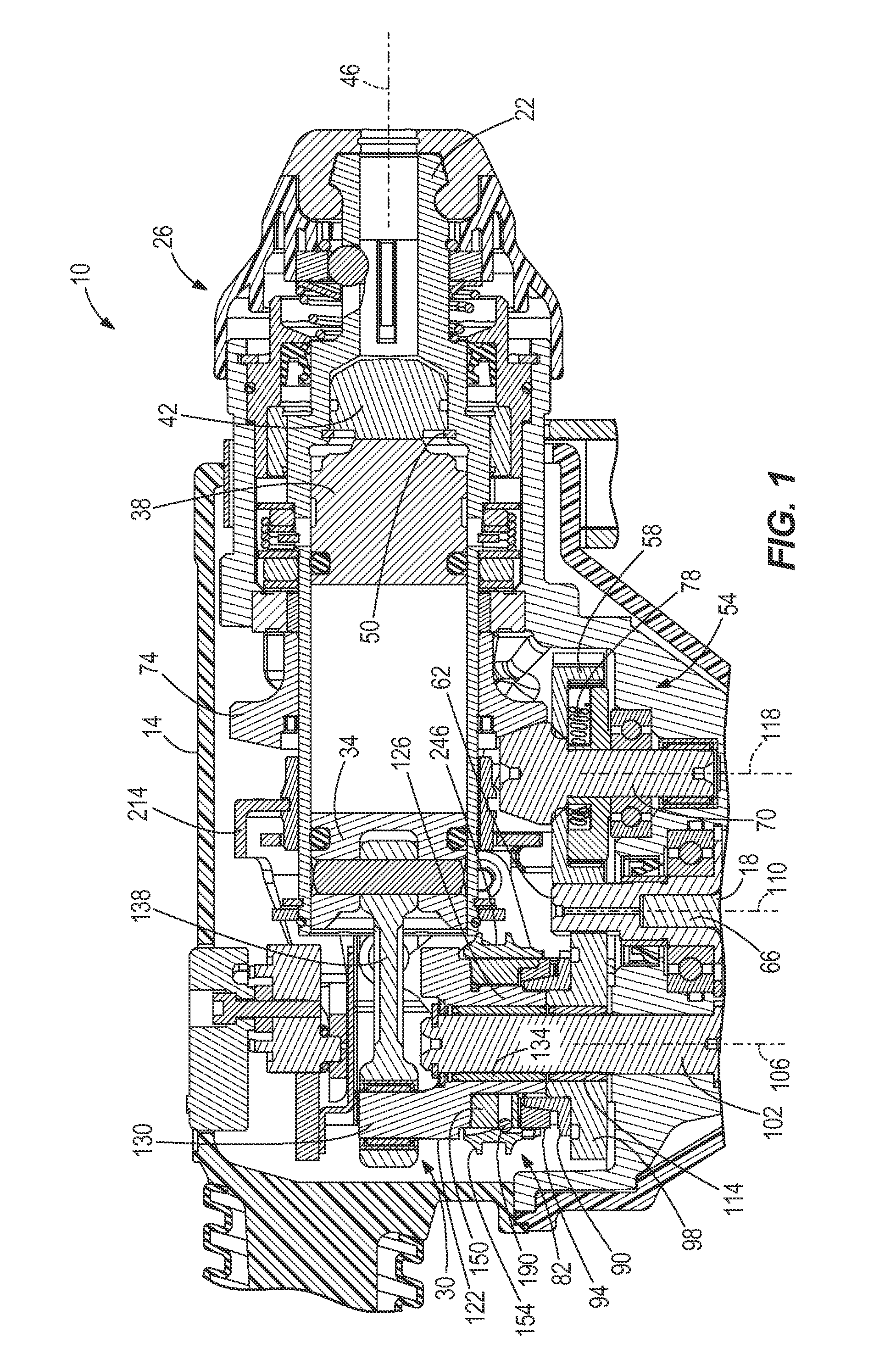
[0031]FIG. 1 illustrates a portion of a rotary hammer 10 according to an embodiment of the invention. The rotary hammer 10 includes a housing 14, a motor 18 disposed within the housing 14, and a rotatable spindle 22 coupled to the motor 18 for receiving torque from the motor 18. Although not shown, a tool bit may be secured to the spindle 22 for co-rotation with the spindle 22 (e.g., using a spline or a hex fit). In the illustrated construction, the rotary hammer 10 includes a quick-release mechanism 26 coupled for co-rotation with the spindle 22 to facilitate quick removal and replacement of different tool bits. The tool bit may include a necked section or a groove in which a detent member of the quick-release mechanism 26 is received to constrain axial movement of the tool bit to the length of the necked section or groove.

[0032]The motor 18 is configured as a DC motor that receives power from an on-board power source (e.g., a battery). The battery may include any of a number of di...


PUM

PropertyMeasurementUnit
Shapeaaaaaaaaaa

Abstract

A rotary power tool includes a housing, a tool element defining a working axis, and a handle coupled to the housing. The handle is movable along a first axis parallel with the working axis between a retracted position and an extended position. The handle includes an upper portion and a lower portion. The rotary power tool also includes an upper joint coupling the upper portion of the handle to the housing and a lower joint coupling the lower portion of the handle to the housing. Each of the upper and lower joints includes a rod extending into the handle and a biasing member disposed between the handle and the housing. The biasing member is operable to bias the handle toward the extended position. Each of the upper and lower joints is operable to attenuate vibration transmitted along the first axis and along a second axis orthogonal to the first axis.

Description

CROSS-REFERENCE TO RELATED APPLICATIONS[0001]This application claims priority to co-pending U.S. Provisional Patent Application No. 61 / 594,675 filed on Feb. 3, 2012, Application No. 61 / 737,304 filed on Dec. 14, 2012, and Application No. 61 / 737,318 filed on Dec. 14, 2012, the entire contents of all of which are incorporated herein by reference.FIELD OF THE INVENTION[0002]The present invention relates to power tools, and more particularly to rotary hammers.BACKGROUND OF THE INVENTION[0003]Rotary hammers typically include a rotatable spindle, a reciprocating piston within the spindle, and a striker that is selectively reciprocable within the piston in response to an air pocket developed between the piston and the striker. Rotary hammers also typically include an anvil that is impacted by the striker when the striker reciprocates within the piston. The impact between the striker and the anvil is transferred to a tool bit, causing it to reciprocate for performing work on a work piece. Th...

Claims


Application Information

Patent Timeline
IPC IPC(8): B25D17/24
CPCB25D17/24B25D16/006B25D11/125B25D17/043B25D2216/0038B25D2250/035B25D2250/131B25D2216/0015B25D2216/0023B25D11/005B25D2222/69B25D2211/003B25G1/01B25D16/003
Inventor WYLER, ANDREW R.
Owner MILWAUKEE ELECTRIC TOOL CORP
Why Eureka
Try Eureka