Electronic viewfinder

Active Publication Date: 2013-08-08
ABILITY ENTERPRISE CO LTD
View PDF8 Cites 1 Cited by
  • Summary
  • Abstract
  • Description
  • Claims
  • Application Information

AI Technical Summary

Benefits of technology

The present invention proposes an electronic viewfinder that can achieve high-magnification, high-resolution, and high levels of comfort while being cost-effective. It provides an adjustable apparatus that can magnify and clearly transmit images to observers in a limited space, and also offers the best eye relief for different observers.

Problems solved by technology

Electronic viewfinders become increasingly slimmer and lighter in recent times. However, magnification or resolution of the images shown in the electronic viewfinder and the ease of use can not be optimized for different observers.

Method used


Image

  • Electronic viewfinder
  • Electronic viewfinder
  • Electronic viewfinder

Examples


Embodiment Construction

[0018]The embodiments of the present invention are described more fully hereinafter with reference to the accompanying drawings, which form a part hereof, and which show, by way of illustration, specific exemplary embodiments by which the invention may be practiced. This invention may, however, be embodied in many different forms and should not be construed as limited to the embodiments set forth herein; rather, these embodiments are provided so that this disclosure will be thorough and complete, and will fully convey the scope of the invention to those skilled in the art.

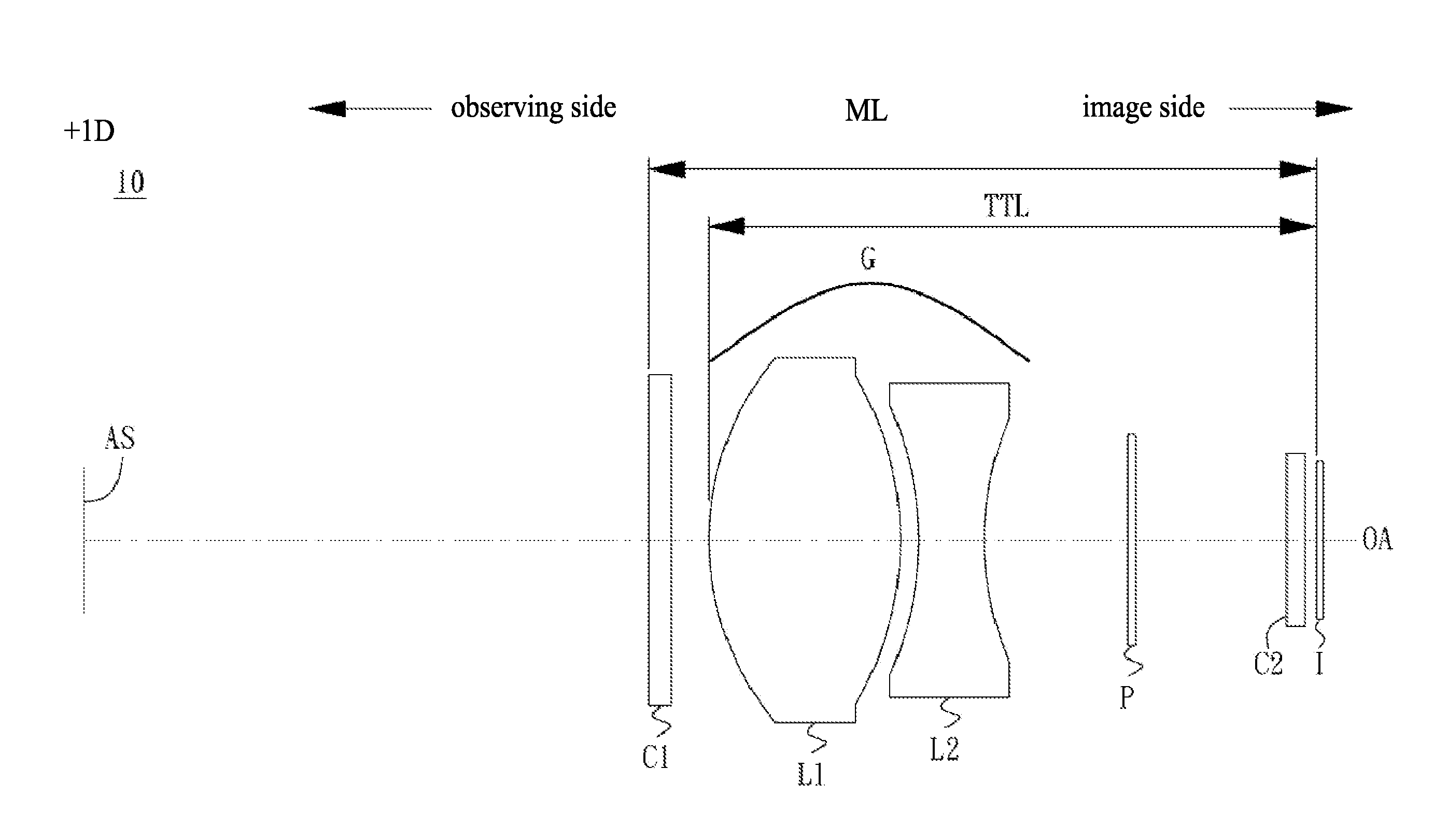
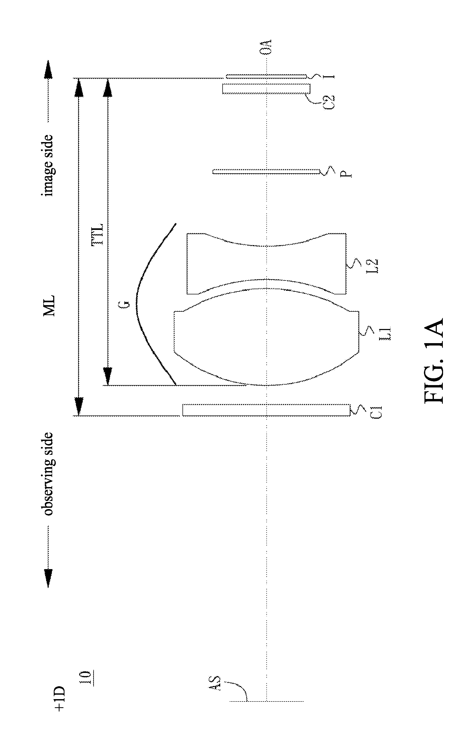
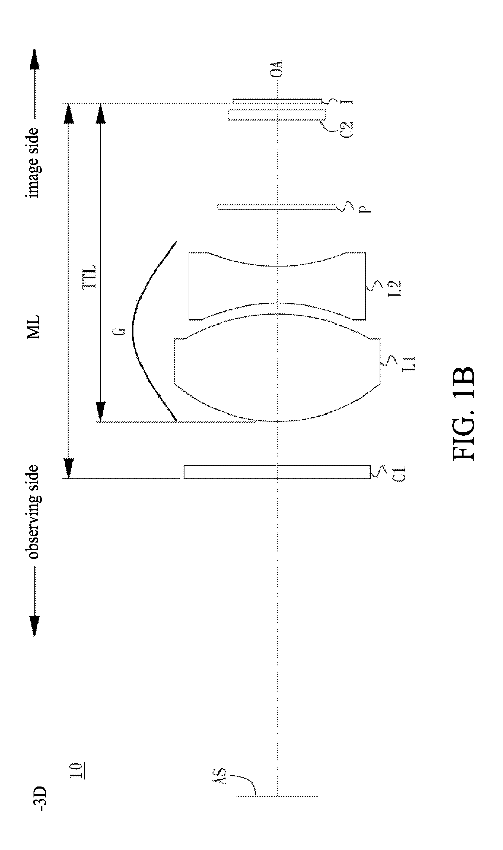
[0019]The present invention is related to an electronic viewfinder located in a limited predetermined space. The diopter in the present invention is adjustable for different observers, for each observer may have his / her own least distance of distinct vision (LDDV). Observers can clearly see images shown on the display of the electronic viewfinder. In one of the embodiments, the electronic viewfinder includes: a fir...


PUM


Abstract

An electronic viewfinder is configured to magnify an image and provide adjustable diopter for different observers. The electronic viewfinder includes an aperture stop, a lens group totally with positive power, and a display. The components in the electronic viewfinder are arranged sequentially between the observer and the image. The lens group is utilized to enlarge the image, and the lens group includes a first lens with positive power and a second lens with negative power. The display is for showing the image. A first planar lens is disposed between the aperture stop and the lens group. A second planar lens may be disposed between the lens group and the display. A polarizer may be arranged between the second planar lens and the lens group.

Description

BACKGROUND[0001]1. Technical Field[0002]The present invention relates to an electronic viewfinder and, in particular, a thin, low-cost, high-magnification, high-resolution, and diopter adjustable viewfinder with increased comfort for the observer.[0003]2. Description of Related Arts[0004]Image capture devices can be used for digital camcorders or cameras that retrieve images of objects by zoom lenses and image sensors. For some image capture devices, the observer can further view objects through an electronic viewfinder.[0005]Electronic viewfinders become increasingly slimmer and lighter in recent times. However, magnification or resolution of the images shown in the electronic viewfinder and the ease of use can not be optimized for different observers.SUMMARY[0006]One of the embodiments of the present invention is to propose an electronic viewfinder which can achieve high-magnification, high-resolution, a high level of comfort and that is cost-effective.[0007]Each observer has his / ...

Claims


Application Information

Patent Timeline
IPC IPC(8): H04N5/232
CPCH04N5/23293H04N23/53
Inventor SHEU, JER-YUAN
Owner ABILITY ENTERPRISE CO LTD
Why Eureka
Try Eureka