Conduit and method of forming

Active Publication Date: 2006-05-25
FISHER & PAYKEL HEALTHCARE
View PDF87 Cites 1 Cited by
  • Summary
  • Abstract
  • Description
  • Claims
  • Application Information

AI Technical Summary

Benefits of technology

[0005] In assisted breathing, particularly in medical applications, gases are supplied and returned through conduits. Such conduits are ideally light and flexible to achieve the highest possible level of comfort for the patient. In the prior art, thin walled conduits ar

Problems solved by technology

A disadvantage with this forming technique is the difficulty welding several adjacent layers.
This problem is especially severe when multiple layer conduit walls are to be formed.
While combining the application of a molten bead with another secon

Method used


Image

  • Conduit and method of forming
  • Conduit and method of forming
  • Conduit and method of forming

Examples


Example

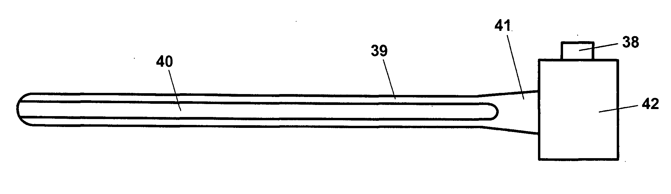
[0053] The present invention relates to breathing conduits in general and in particular to improved methods of forming thin film (tape or ribbon) spiral wound conduits. Consequently the present invention finds application in breathing conduits fabricated from a variety of materials which may include breathable and / or non-breathable materials (breathable materials being capable of transmitting water vapour but not liquid water).

[0054] In assisted breathing, particularly in medical applications, gases having high levels of relative humidity are supplied and returned through conduits of a relatively restricted size. Build up of condensation on the inside wall of the conduit is a potential result of this high humidity. The purpose of including a breathable region or regions in the conduit wall is to allow diffusion of water vapour from the expiratory limb of the breathing circuit along the path thereof. This can reduce the build up of condensation within the expiratory limb by drying t...


PUM


Abstract

A thin ribbon spirally wound polymer conduit and method of forming, wherein a helical reinforcing bead is interposed adjacent overlapping layers of ribbon. Further, a method of continuously forming spirally wound conduit wherein a sacrificial layer, preferably having a different base polymer to that of the conduit, is first applied to the former before the conduit is formed overtop.

Description

RELATED APPLICATION (PRIORITY CLAIM) [0001] This patent application is a divisional of U.S. patent application Ser. No. 10 / 656,574, filed Sep. 5, 2003 and entitled “Conduit and Method of Forming”, which claims priority from New Zealand Patent Application No. 521274, filed Sep. 9, 2002 and New Zealand Patent Application No. 521364, filed Sep. 11, 2002.BACKGROUND TO THE INVENTION [0002] 1. Field of the Invention [0003] The present invention relates to components for breathing circuits and in particular to conduits for use in the limbs of breathing circuits. The invention also relates to methods of manufacturing such conduits. [0004] 2. Summary of the Prior Art [0005] In assisted breathing, particularly in medical applications, gases are supplied and returned through conduits. Such conduits are ideally light and flexible to achieve the highest possible level of comfort for the patient. In the prior art, thin walled conduits are known which include helical or annular reinforcing ribs wh...

Claims


Application Information

Patent Timeline
IPC IPC(8): B29C63/00A61L29/00A61M11/08A61M16/08B29C48/09B29C48/10B29C48/13B29C48/151B29C48/19B29C53/36B29C53/58B29C53/60B29C53/64B29C53/80B29C59/00B29C65/00B29C65/02B29C65/18B29C65/40B29L23/00F16L9/16F16L11/115F16L11/24
CPCA61M11/08Y10T156/1132B29C47/0023B29C47/0038B29C47/021B29C53/36B29C53/582B29C53/60B29C53/607B29C59/007B29C63/0013B29C65/18B29C65/40B29C66/1122B29C66/81457B29C66/83413B29C66/83415B29C2053/365B29L2023/007B29L2023/18F16L9/16F16L11/115F16L11/24A61M16/08Y10T428/139B29C47/0033B29C47/062B29C66/4322B29C66/4329B29C66/431Y10T156/1944Y10T156/19Y10T156/11B29C65/10B29C66/112B29C66/135B29C66/49B29C66/496B29C66/71B29C66/723B29C48/10B29C48/13B29C48/0021B29C48/151B29C48/001B29C48/09B29C48/19A61M16/1095A61M2207/10B29K2023/12A61M16/0875B32B37/1284B32B37/142B32B38/10A61M2207/00B29C63/0073B29C63/065B32B37/26B32B2037/268B32B2535/00
Inventor SMITH, DANIEL JOHNGRAY, NATHAN LEESKELTON, BLAIR VICTOR
Owner FISHER & PAYKEL HEALTHCARE
Why Eureka
Try Eureka