
Robust torch jet spark plug electrode

Inactive Publication Date: 2002-08-22
SAVAGE ENTERPRISES
View PDF0 Cites 5 Cited by
  • Summary
  • Abstract
  • Description
  • Claims
  • Application Information

AI Technical Summary

Benefits of technology

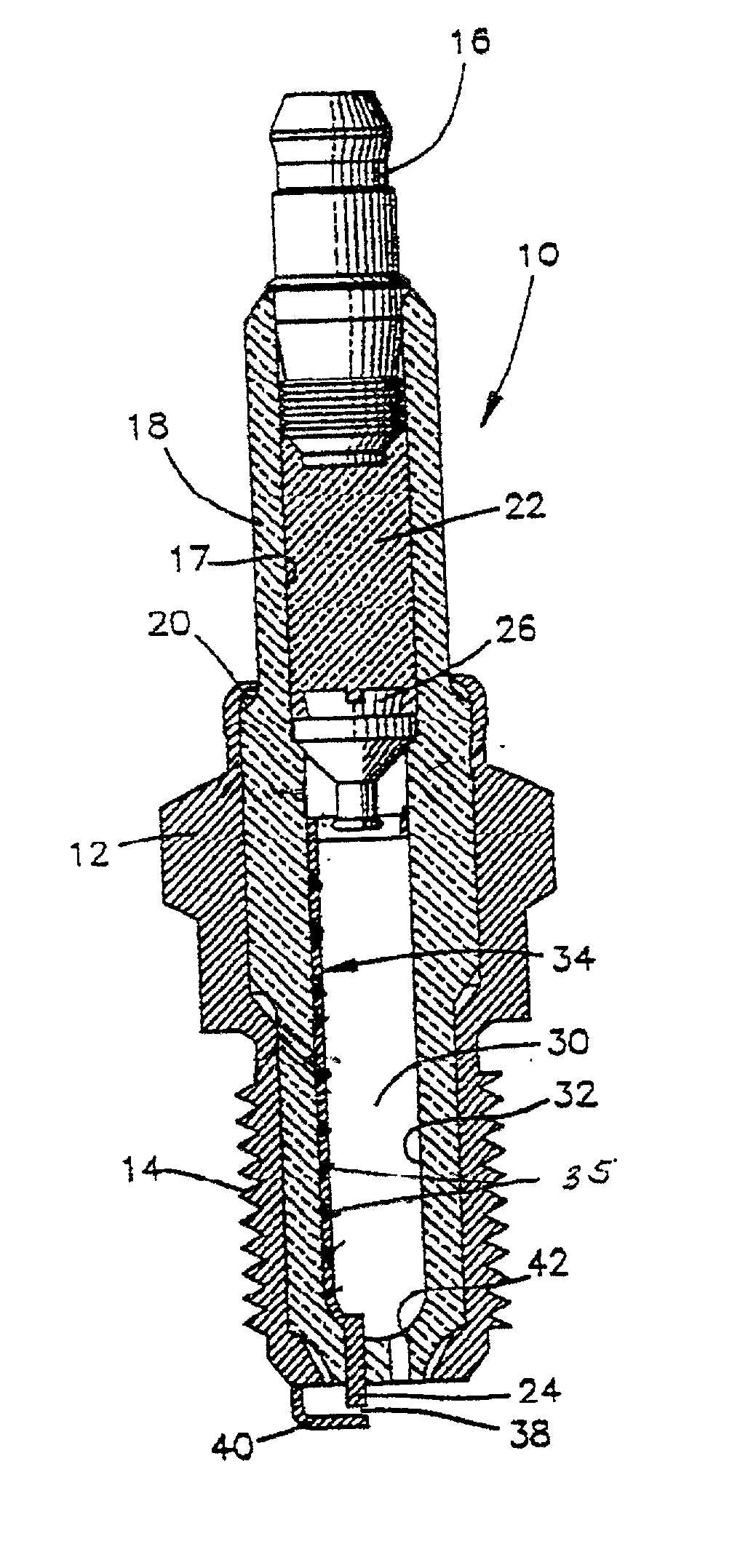
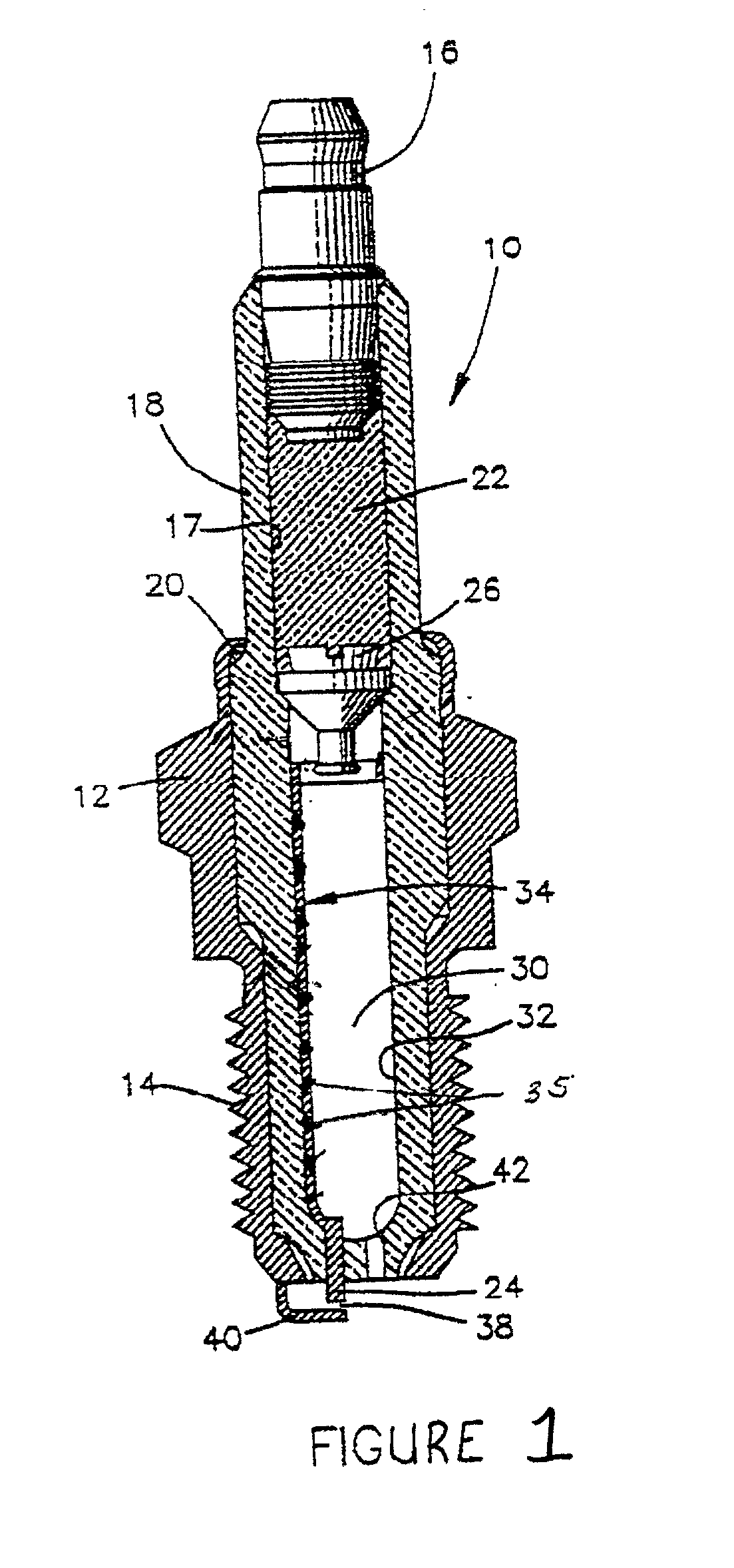
[0010] It is, therefore, an objective of the invention to provide a torch jet spark plug having a durable electrode which has good resistance to explosive erosion mechanisms.
[0011] A further objective is to produce a torch jet spark plug having an electrode which has a rough surface that creates a stagnant boundary layer near the electrode surface to reduce spark erosion.
[0017] A method of forming the electrode is also provided. The method comprises several steps. The initial step involves injecting the electrode composition within a ceramic insulator body of the spark plug to deposit an electrode layer therein. The electrode layer and the ceramic insulator body are then co-fired so that the electrically conductive material sinters to form a conductive electrode embedded within the ceramic insulator body. The electrically conductive material also forms ribbons around the ceramic particles so as to produce an electrode resistant to explosive erosion mechanisms, which consequently increases the life of the torch jet spark plug.

Problems solved by technology

Lower sparking voltages means decreased burn rate, high fuel consumption, and higher emissions.
Higher sparking voltages around 30,000 volts or higher, leads to breakdown of the electrical system, spark plug wires, etc.
Higher sparking also causes higher radio noise and radio frequency interference.
During testing, the plugs produced by the Durling et al. and the Polikarpus et al. techniques did not perform as desired, often failing to meet the minimum desired 100 hours of accelerated testing.
One of the factors leading to this premature failure appears to be deposits from the engine such as calcium phosphate at the tip.
Electrode wear can cause premature spark plug failure and the voltage necessary for "sparking" may reach unacceptable levels.

Method used


Image

  • Robust torch jet spark plug electrode
  • Robust torch jet spark plug electrode

Examples


example 2

[0035] a) 9.0 grams Condea Vista SCFA-100 gamma alumina

[0036] b) 21.0 grams Degussa platinum / rhodium flake 90 / 10

[0037] c) 20.0 grams ethanol

[0038] d) 5.0 grams terpineol

[0039] e) 25.0 grams xylene

example 3

[0040] a) 9.0 grams Alcoa A-16 SG alpha alumina

[0041] b) 21.0 grams Degussa H-7000 platinum powder

[0042] c) 20.0 grams ethanol

[0043] d) 34.0 grams terpineol

[0044] e) 5.0 grams cellulose ethylether resin

[0045] f) 5.0 grams butyl acetate

[0046] A spark plug fails when the voltage necessary to initiate a spark increases over 25,000 to 30,000 volts. The electrical system cannot supply more voltage than approximately 30,000 volts. The following table compares the voltage capabilities of spark plugs having different types of electrodes. Note that some of the plugs produced a spark with 33,000 and 32,000 volts but the spark was irregular so that plugs were considered to have failed. The others "failed" because a spark no longer occurred and thus the demand voltage could not be measured.

1 Demand Voltage New 100 Hour 200 Hour 300 Hour 400 Hour Standard 16,000 18,000 22,000 22,000 failed platinum tip plug Torch jet 15,000 33,000 32,000 failed failed by inked (failed) (failed) spindle Torch jet...


PUM

PropertyMeasurementUnit
Percent by massaaaaaaaaaa
Thicknessaaaaaaaaaa
Electrical conductivityaaaaaaaaaa

Abstract

A composition for forming an electrode for use in a torch jet spark plug is provided. The composition comprises a ceramic material, ceramic particles, and an electrically conductive material. The ceramic particles are dispersed within the ceramic material. At least some of the ceramic particles have a predetermined size. This predetermined size is at least as large as the thickness of the finally formed electrode. The electrically conductive material is capable of being manipulated to form ribbons around the ceramic particles and of being sintered to form the electrode. The resultant electrode has good resistance to explosive erosion mechanisms, which consequently increases the life of the torch jet spark plug.

Description

[0001] The invention relates, in general, to torch jet spark plugs for use within a main combustion chamber of an internal combustion engine. More particularly, the invention relates to a durable, coarse particle electrode for a torch jet spark plug.[0002] The following background information is provided to assist the reader to understand the environment in which the invention will typically be used. The terms used herein are not intended to be limited to any particular narrow interpretation unless specifically stated otherwise in this document.[0003] A spark plug is a device, inserted into the combustion chamber of an engine, containing a side electrode and an insulated center electrode spaced to provide a gap for firing an electrical spark to ignite air-fuel mixtures. The high-voltage burst from the coil via the distributor is received at the spark plug's terminal and conducted down a center electrode protected by an insulator. At the bottom of the plug, which projects into the cy...

Claims


Application Information

Patent Timeline
IPC IPC(8): F02P13/00C22C5/04C22C29/12C22C32/00H01T13/20H01T13/34H01T13/39H01T13/50H01T13/54H01T21/02
CPCH01T13/50H01T13/54
Inventor LABARGE, WILLIAM J.POLIKARPUS, KAIUS KIIRENBRENSKE, KEITH MICHAEL
Owner SAVAGE ENTERPRISES
Learn More