
Supra-threshold test and a sub-pixel strategy for use in measurements across the field of vision

a subpixel and test technology, applied in the field of suprathreshold test and subpixel strategy for use in measurements across the field of vision, can solve problems such as uncertainty, and achieve the effects of improving the high sensitivity end of the dynamic test range, increasing displacement, and improving precision

Active Publication Date: 2013-08-08
UCL BUSINESS PLC
View PDF4 Cites 11 Cited by
  • Summary
  • Abstract
  • Description
  • Claims
  • Application Information

AI Technical Summary

Benefits of technology

The patent describes a method and apparatus for conducting a motion displacement test to determine if a person has lost visual sensitivity in a specific location. By combining results from multiple cluster locations, the method allows for a more reliable and faster determination of the test results. The test uses sub-pixels in a display feature, such as a vertical line, to determine the position of the stimulus energy relative to the background. The sub-pixels produce the same output energy, so the display feature has a constant output energy at different positions. The method also involves presenting stimuli with different displacement patterns and measuring the displacement at which the stimulus first becomes visible. The use of sub-pixellation rendering improves the high sensitivity end of the test range and allows for more accurate assessment of the displacement at which a stimulus first becomes visible. The display feature can take different shapes or designs, and the direction of movement can be horizontal or not. The sub-pixels are evenly spaced in a direction parallel to the direction of movement in one embodiment. The technical effects of the patent are improved accuracy and speed in determining if a person has lost visual sensitivity in a specific location.

Problems solved by technology

It will be appreciated that these intermediate results represent uncertainty, in that the relevant location does not have a clear seen or unseen status.

Method used


Image

  • Supra-threshold test and a sub-pixel strategy for use in measurements across the field of vision
  • Supra-threshold test and a sub-pixel strategy for use in measurements across the field of vision
  • Supra-threshold test and a sub-pixel strategy for use in measurements across the field of vision

Examples


Embodiment Construction

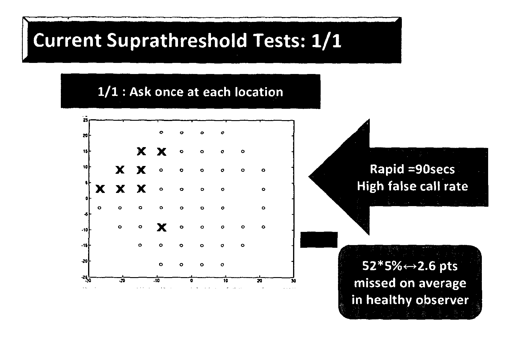
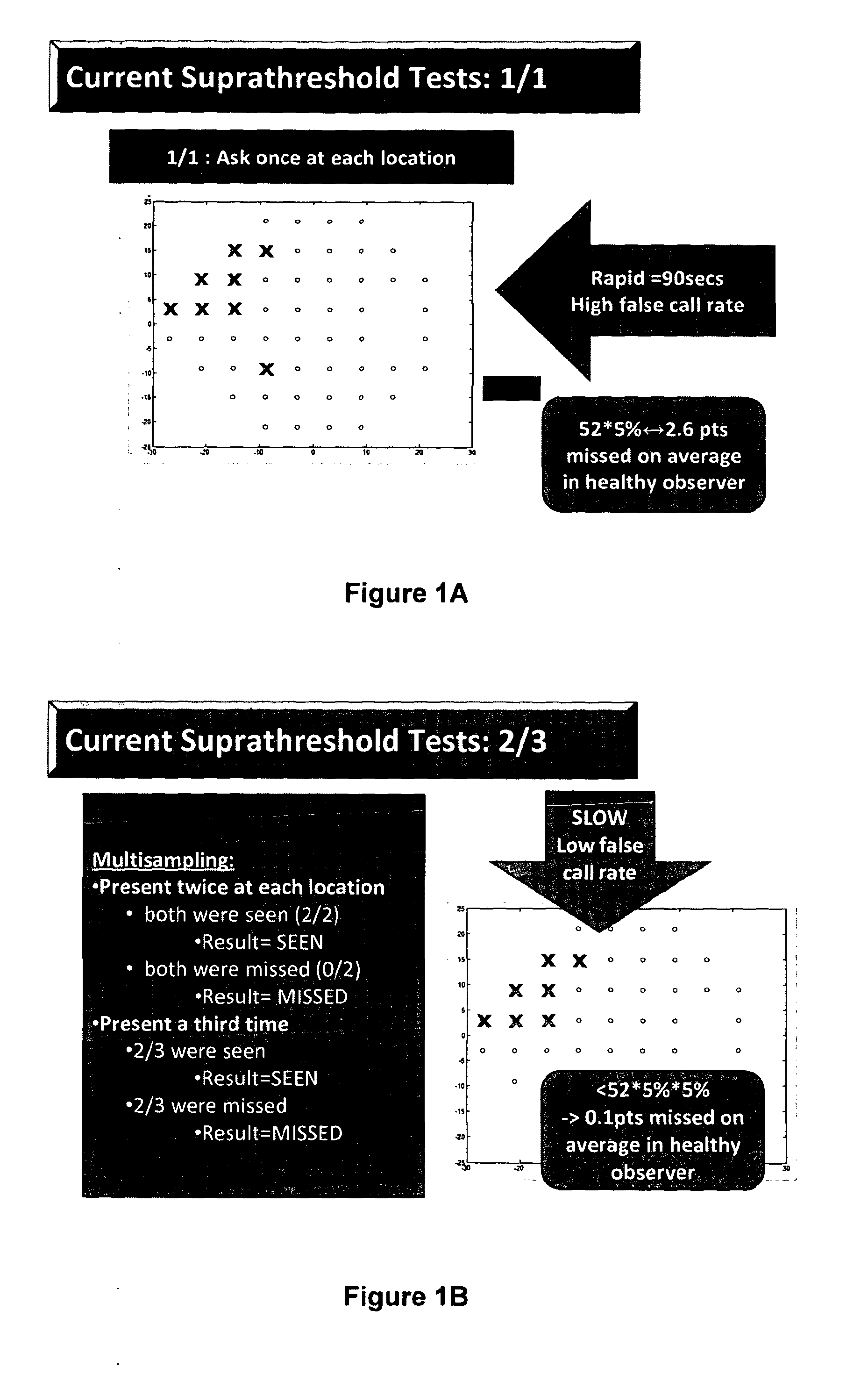
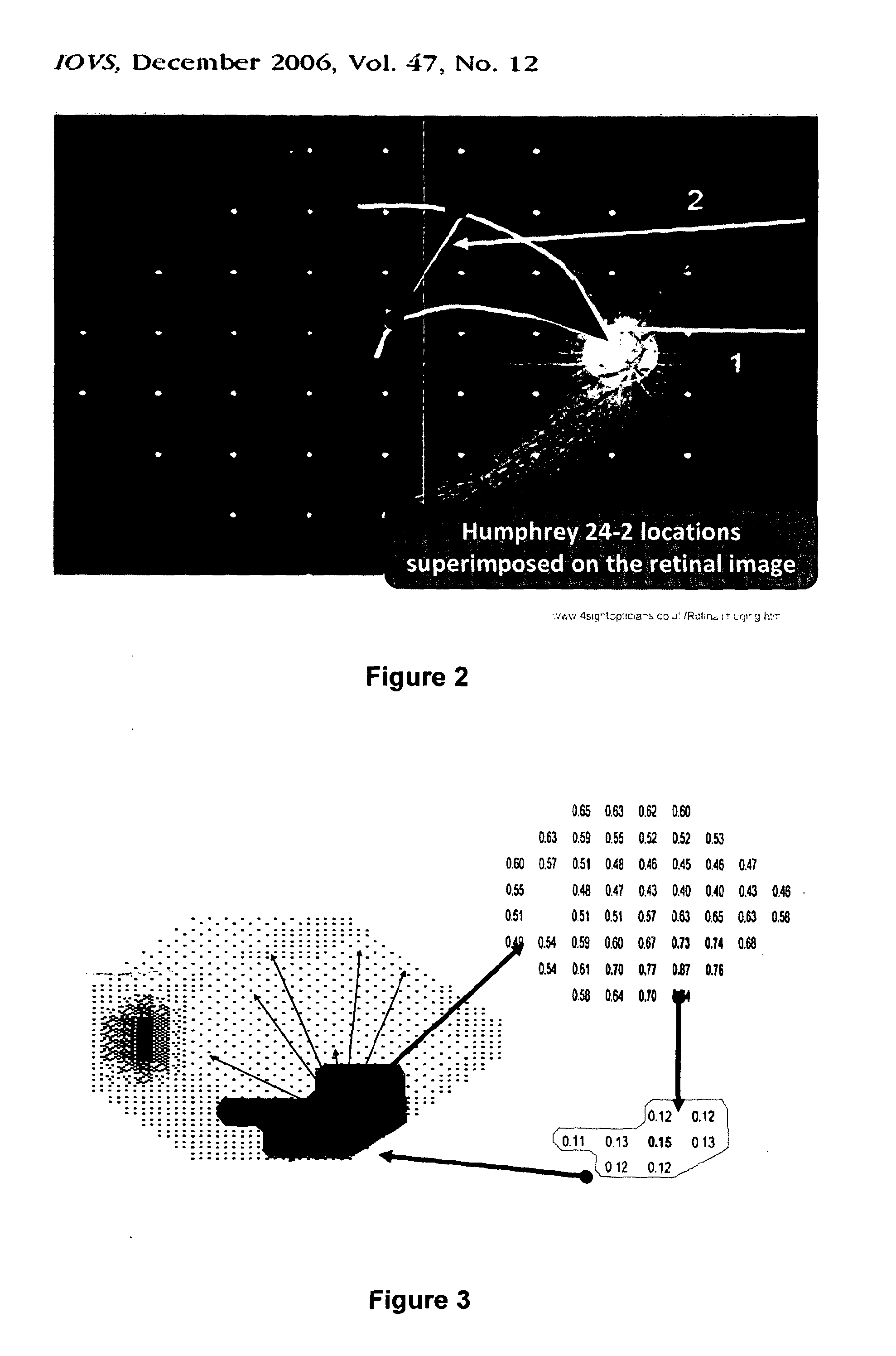
[0043]The present approach provides a suprathreshold visual field test in which cluster analysis is used for the retest strategy, in other words for determining which locations to retest and which locations not to retest. The cluster analysis incorporates physiological information concerning the spatial arrangement of optical nerve fibres across the retina. In particular, it is recognised that that if a given optical nerve fibre is damaged, then damage is more likely at test locations clustered on or close to the path of the optical nerve fibre. Conversely, if a given optical nerve fibre is healthy and working properly, this correct operation is likewise more likely at test locations clustered on or close to the path of the optical nerve fibre.

[0044]According to the present approach, locations in a healthy cluster are immediately eliminated from retest, whereas large points in a cluster that have been flagged as damaged during an initial part of the test sequence are isolated and re...


PUM


Abstract

One embodiment of the invention provides a method for performing a supra-threshold test of sensitivity across a visual field of a subject. The method includes presenting a stimulus at each location of a set of locations spread across the visual field and obtaining for each stimulus a result indicating whether or not the stimulus was seen by the subject. The method further includes determining for each location whether or not to re-present a stimulus at that location, wherein for a given location, the determining involves combining results obtained from multiple locations. These multiple locations are defined by a cluster associated with the given location, with the cluster being determined based on the paths of optic nerve fibre bundles across the visual field.

Description

FIELD OF THE INVENTION[0001]The present invention relates to a supra-threshold test for use in detecting sensitivity loss across the field of vision, for example, to identify or investigate glaucoma, and a sub-pixel strategy for use in measurements across the field of vision.BACKGROUND OF THE INVENTION[0002]Glaucoma describes a group of conditions which have in common progressive optic neuropathy with associated patterns of visual field loss. There are various known techniques to detect the presence of visual field loss due to glaucoma. One such known technique is the Moorfields Motion Displacement Test (MDT) which has been developed by a collaboration between Moorfields Eye Hospital, London, the UCL Institute of Ophthalmology and City University London, see Fitzke et al 1987, Verdon-Roe et al 2006a and Verdon-Roe et al 2006b (CE Mark Registered Number CE 2006 / 0012, Date: 14 Jul. 2006, Manufacturer AC Viswanathan).[0003]The Moorfields MDT involves the presentation of a pattern of mu...

Claims


Application Information

Patent Timeline
Patent Type & Authority Applications(United States)
IPC IPC(8): A61B3/024
CPCA61B3/024
Inventor CRABB, DAVIDBERGIN, CIARAGARWAY-HEATH, DAVIDVERDON-ROE, GAYWESTCOTT, MARK
Owner UCL BUSINESS PLC
Learn More