Image forming apparatus

Active Publication Date: 2013-08-08
CANON KK
View PDF9 Cites 6 Cited by
  • Summary
  • Abstract
  • Description
  • Claims
  • Application Information

AI Technical Summary

Benefits of technology

[0013]The present invention provides an image forming apparatus capable of keeping a toner concentration of a developer within a tolerance range over a long term even if image

Problems solved by technology

If the toner concentration drops below the lower limit value, the normal operation of the developing device can no longer be continued.
Therefore, if the image formation exhibiting extremely small toner consumption is continuously performed, the toner concentration of the developer inside t

Method used


Image

  • Image forming apparatus
  • Image forming apparatus
  • Image forming apparatus

Examples


first embodiment

[0099]FIG. 10 is a flowchart of toner charge amount control according to a first embodiment of the present invention.

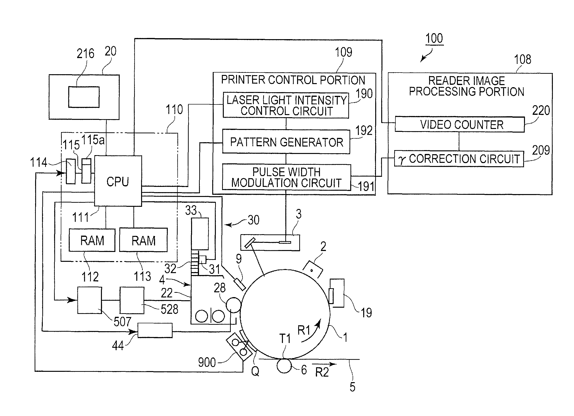
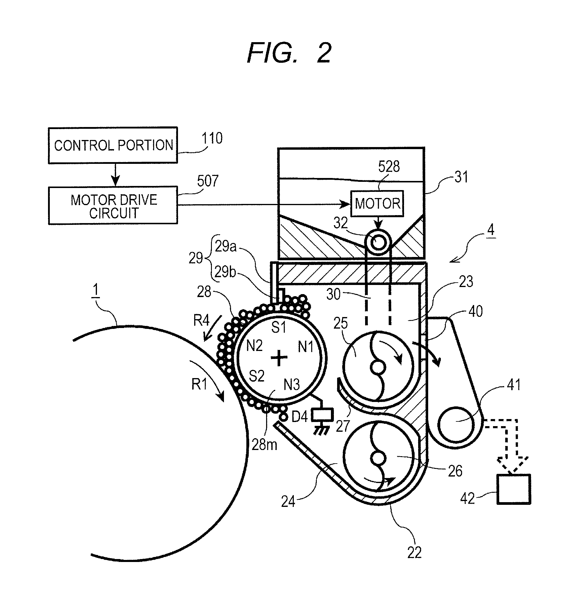
[0100]As illustrated in FIG. 4, the exposure device 3 exemplifying an electrostatic image forming unit forms the electrostatic image of an image on the photosensitive drum 1 exemplifying the image bearing member. The developing device 4 causes the developer including the charged toner to be carried on the developing sleeve 28 exemplifying the developer carrying member, and applies a voltage thereto. With this operation, the developing device 4 develops the electrostatic image into the toner image having the toner borne-on quantity corresponding to the development contrast being the potential difference between the potential of the developing sleeve 28 and the potential of the electrostatic image. The hopper 31 exemplifying a replenishment unit replenishes the developing device 4 with the developer in order to compensate the toner consumed in the image formation. In ea...

second embodiment

[0126]FIG. 11 is an explanatory graph illustrating the setting of the target value for patch detection ATR control according to a second embodiment of the present invention. In the first embodiment, the target value of the toner borne-on quantity of the patch detection ATR is changed to lift the replenishment restriction for the replenishment developer, while in the second embodiment, the development contrast at the time of the ATR patch formation is changed to lift the replenishment restriction for the replenishment developer.

[0127]As illustrated in FIG. 4, based on the detection result for the ATR patch, at the frequency equal to or lower than ½ of the frequency at which the hopper 31 is controlled, the control portion 110 exemplifying the setting unit sets the first development contrast, forms the toner image for measurement, and uses the optical sensor 900 to detect it. Then, the control portion 110 sets the first development contrast itself so that the detected toner borne-on q...

third embodiment

[0139]FIG. 12 is a flowchart of toner charge amount control according to a third embodiment of the present invention.

[0140]In the second embodiment, the development contrast Vcontn+1 used when the ATR patch is output changes, and the target value of the toner borne-on quantity of the ATR patch to be output has always been a fixed constant value since the initial setting of the target value. In contrast thereto, in the third embodiment, in the updating of the target value for the patch detection ATR control, which is executed for each Dmax control, the toner borne-on quantity of the ATR patch to be output is updated to the toner borne-on quantity corresponding to the image density used most by a user.

[0141]In the second embodiment, the ATR patch is output to perform the replenishment control of the replenishment developer so that the toner borne-on quantity of the ATR patch attains the target value. Therefore, the image density, which is obtained when the toner image having the toner...


PUM


Abstract

Patch detection ATR control is executed each time image formation of a predetermined number of sheets is performed, and a replenishment quantity of a replenishment developer to be supplied from a hopper (31) is corrected so that a toner charge amount of a developer included in a developing device (4) becomes closer to a target toner charge amount. Further, Dmax control is executed each time a predetermined number of times of control for correcting the replenishment quantity of the replenishment developer are performed, and a development contrast used for the image formation is set so that a developed toner image attains a maximum density of an output image. A control portion (110) changes the target toner charge amount based on a density of a patch formed in accordance with the Dmax control.

Description

BACKGROUND OF THE INVENTION[0001]1. Field of the Invention[0002]The present invention relates to an image forming apparatus for controlling a replenishment quantity of a developer for a developing device based on a detection result of a toner borne-on quantity of a toner image for control, and more particularly, to control for replacing a part of control for ensuring reproducibility of an image density by adjustment of a toner charge with adjustment of a development contrast.[0003]2. Description of the Related Art[0004]In widely-used image forming apparatus, charged toner adheres to an electrostatic image formed on an image bearing member to develop into a toner image, the toner image is transferred to a recording material directly or through intermediation of an intermediate transfer member, and the recording material onto which the toner image has been transferred is heated and pressurized to fix an image on the recording material. As illustrated in FIG. 6B, in the image forming a...

Claims


Application Information

Patent Timeline
IPC IPC(8): G03G15/08
CPCG03G15/0877G03G15/0856G03G15/0831G03G15/5041G03G2215/00037
Inventor ARIIZUMI, OSAMU
Owner CANON KK
Why Eureka
Try Eureka