Electrical connector

Inactive Publication Date: 2013-08-08
MOLEX INC
View PDF2 Cites 17 Cited by
  • Summary
  • Abstract
  • Description
  • Claims
  • Application Information

AI Technical Summary

Problems solved by technology

Therefore, both the insulating housing and the shielding housing of the conventional electrical connector are disposed above the circuit board, so the total height is large, and gen...

Method used


Image

  • Electrical connector
  • Electrical connector
  • Electrical connector

Examples


Embodiment Construction

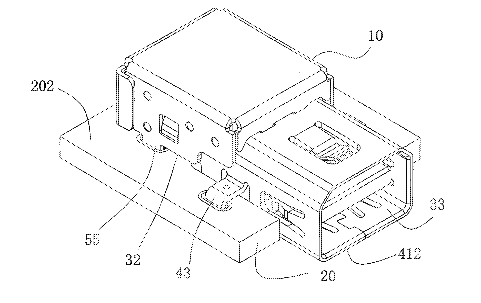
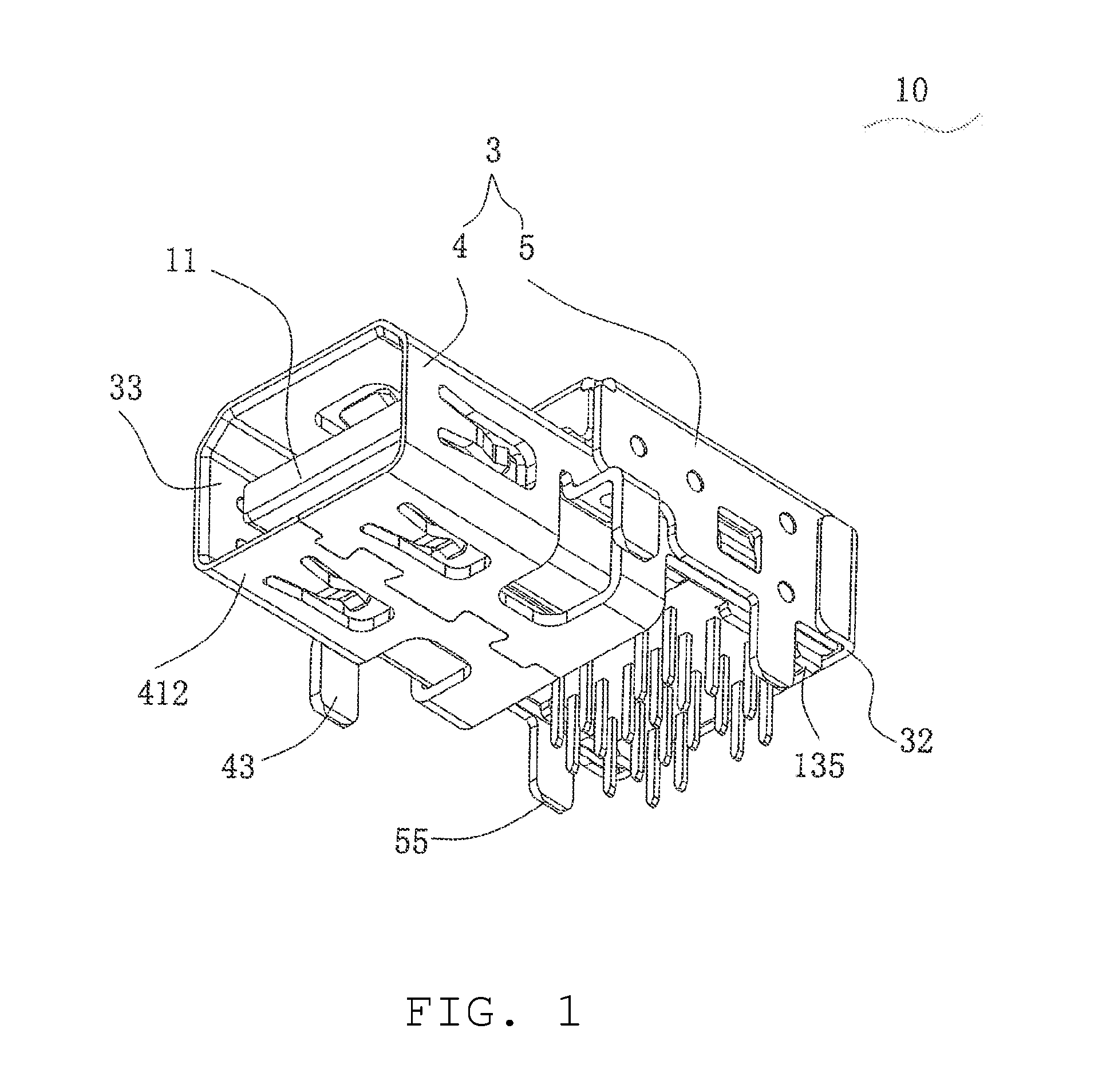
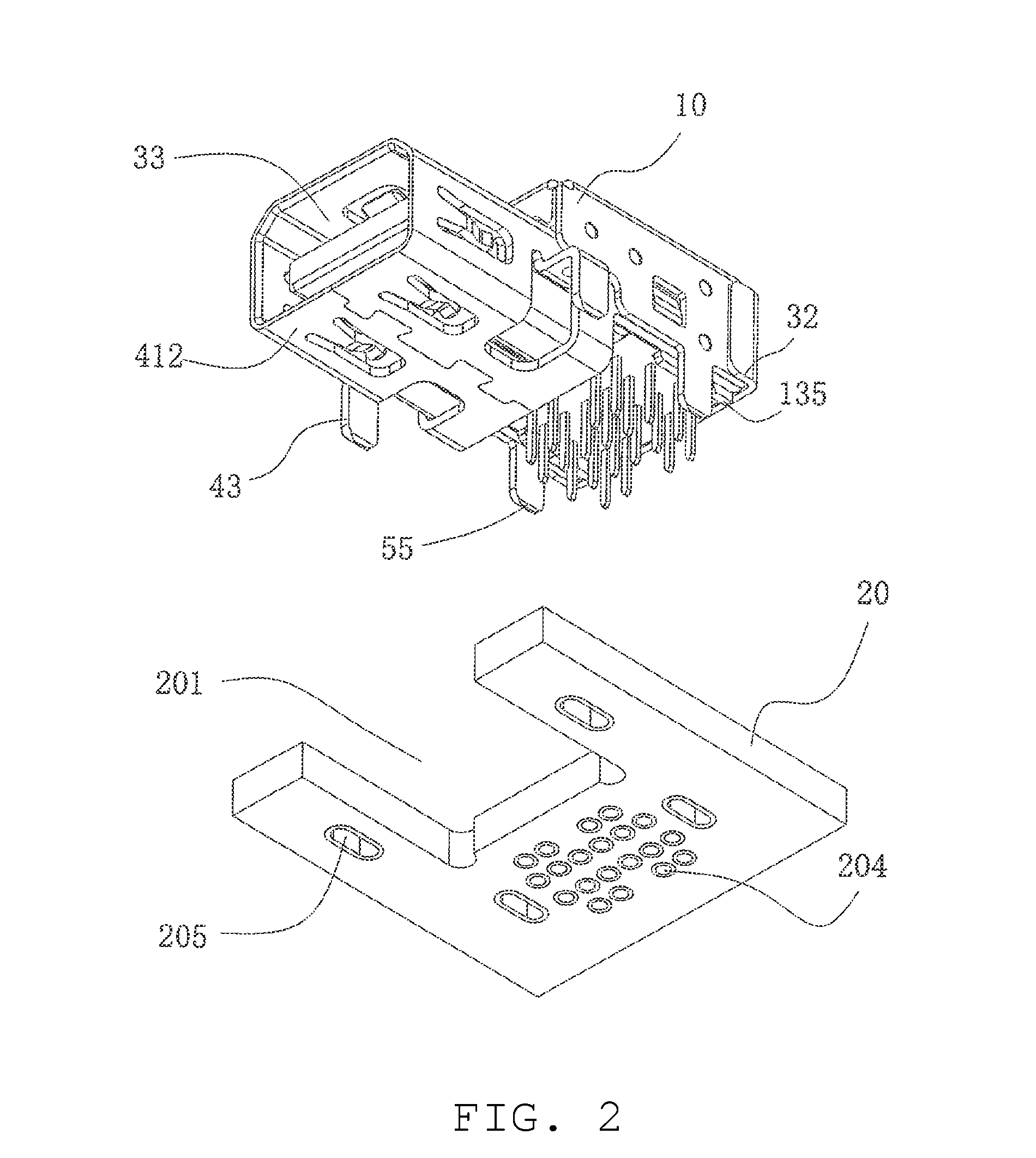
[0022]Hereinafter, by taking the mini-DisplayPort cable connector as an example, the embodiments will be described in detail with reference to the accompanying drawings. The detailed description that follows describes exemplary embodiments and is not intended to be limited to the expressly disclosed combination(s). Therefore, unless otherwise noted, features disclosed herein may be combined together to form additional combinations that were not otherwise shown for purposes of brevity.

[0023]The electrical connector disclosed herein could reduce the total height of the connector and a corresponding circuit board by the structure provided. For example, the front portion of the shield is designed to recessed into the circuit board, thereby reducing the total height of the connector and the circuit board. As a result, the electrical connector is especially adapted to applications such as the notebook computer with compact space. Furthermore, by providing a bending portion upwardly bendin...


PUM


Abstract

An electrical connector includes a body with a tongue and the body supports a terminal module, the terminal module including a first row of terminals and a second row of terminals. Each terminal includes a contact portion and a soldering portion, the contact portions of the first and second row of terminals being disposed on an upper side and a lower side of the tongue, respectively, and the soldering portions of the first and second row of terminals each being arranged in a front column and a back column. A first and second positioning element can support the first and second rows of terminals, respectively. A shield that envelopes a periphery of the insulating body forms a contact chamber for accommodating the tongue. The front portion of the shield can be recessed into the circuit board to reduce the effective height of the connector and circuit board.

Description

RELATED APPLICATIONS[0001]This application claims priority to Chinese Application No. 201010200703.0, filed Jun. 10, 2010, which is incorporated herein by reference in its entirety.TECHNICAL FIELD[0002]The present invention relates to an electrical connector and, in particular, to an electrical connector suitable for helping to reduce the total height of an electrical connector and a corresponding circuit board.BACKGROUND[0003]With the fast development of multi-media technique, Mini-Display Port connectors are widely used in electronic devices day by day. To help meet the desire for miniaturized products, Chinese patent ZL200920001857.X discloses an electrical connector comprising an insulating housing which is provided with an accommodating chamber at the rear portion thereof and a tongue protruding forwardly from the front portion thereof; a plurality of terminals, which include an upper row of terminals mounted at the upper side and a lower row of terminals mounted at the lower s...

Claims


Application Information

Patent Timeline
IPC IPC(8): H01R12/71
CPCH01R12/724H01R13/6594H01R12/716
Inventor ZHANG, XUE-HAI
Owner MOLEX INC
Why Eureka
Try Eureka