
System and method of charging a vehicle using a dynamic power grid, and system and method of managing power consumption in the vehicle

a dynamic power grid and charging system technology, applied in the direction of navigation instruments, driver interactions, and arrangements for several simultaneous batteries, can solve the problems of limited charging time, limited range of actual energy sources for powering the vehicle, and virtually limitless range of actual energy sources. achieve the effect of convenient and efficien

Active Publication Date: 2013-08-08
IBM CORP
View PDF7 Cites 75 Cited by
  • Summary
  • Abstract
  • Description
  • Claims
  • Application Information

AI Technical Summary

Benefits of technology

The patent describes a system and method for charging electric vehicles using a dynamic power grid. The system includes a forward model that predicts charging data for multiple vehicles, and a charge exchange market that facilitates agreements for transmitting power between vehicles. The network can access external databases to gather information about expected weather, traffic, and charging locations, and use that data to optimize the charging process for the vehicles. The goal is to minimize stops, deviation from a planned route, and the risk of running out of charge. Overall, the system and method improve the efficiency and reliability of electric vehicle charging.

Problems solved by technology

Charging time is limited primarily by the capacity of the grid connection.
It is not clear that such batteries will work directly in BEVs as heat build-up may make them unsafe.
Because of the PHEV's capacity to store power from both liquid fuels and the electric power grid, the range of actual energy sources for powering the vehicle is virtually limitless.
This is the only mode that a battery electric vehicle can operate in, hence their limited range.

Method used


Image

  • System and method of charging a vehicle using a dynamic power grid, and system and method of managing power consumption in the vehicle
  • System and method of charging a vehicle using a dynamic power grid, and system and method of managing power consumption in the vehicle
  • System and method of charging a vehicle using a dynamic power grid, and system and method of managing power consumption in the vehicle

Examples


Embodiment Construction

[0044]Referring now to the drawings, FIGS. 1-13 illustrate the exemplary aspects of the present invention.

Charging a Vehicle

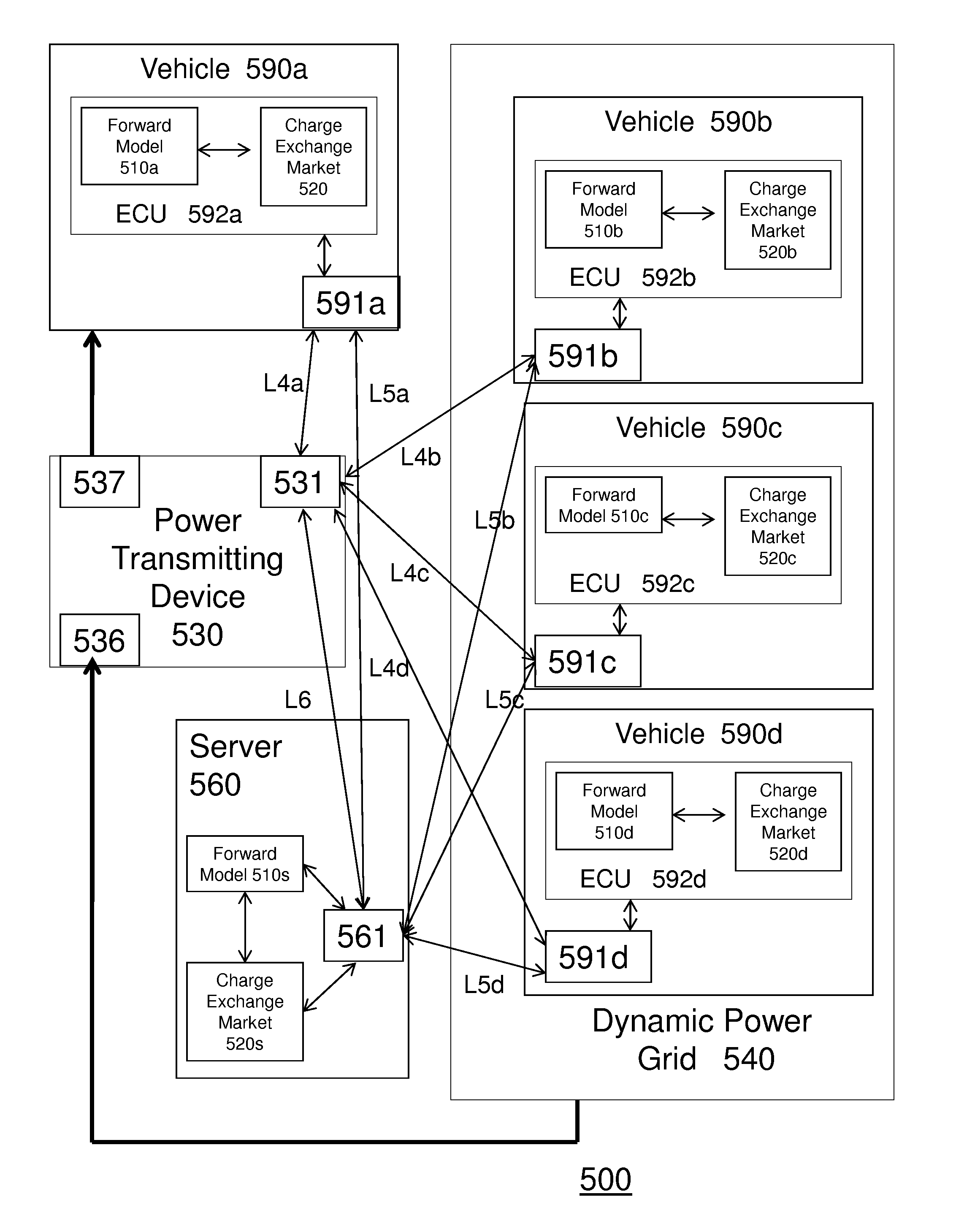
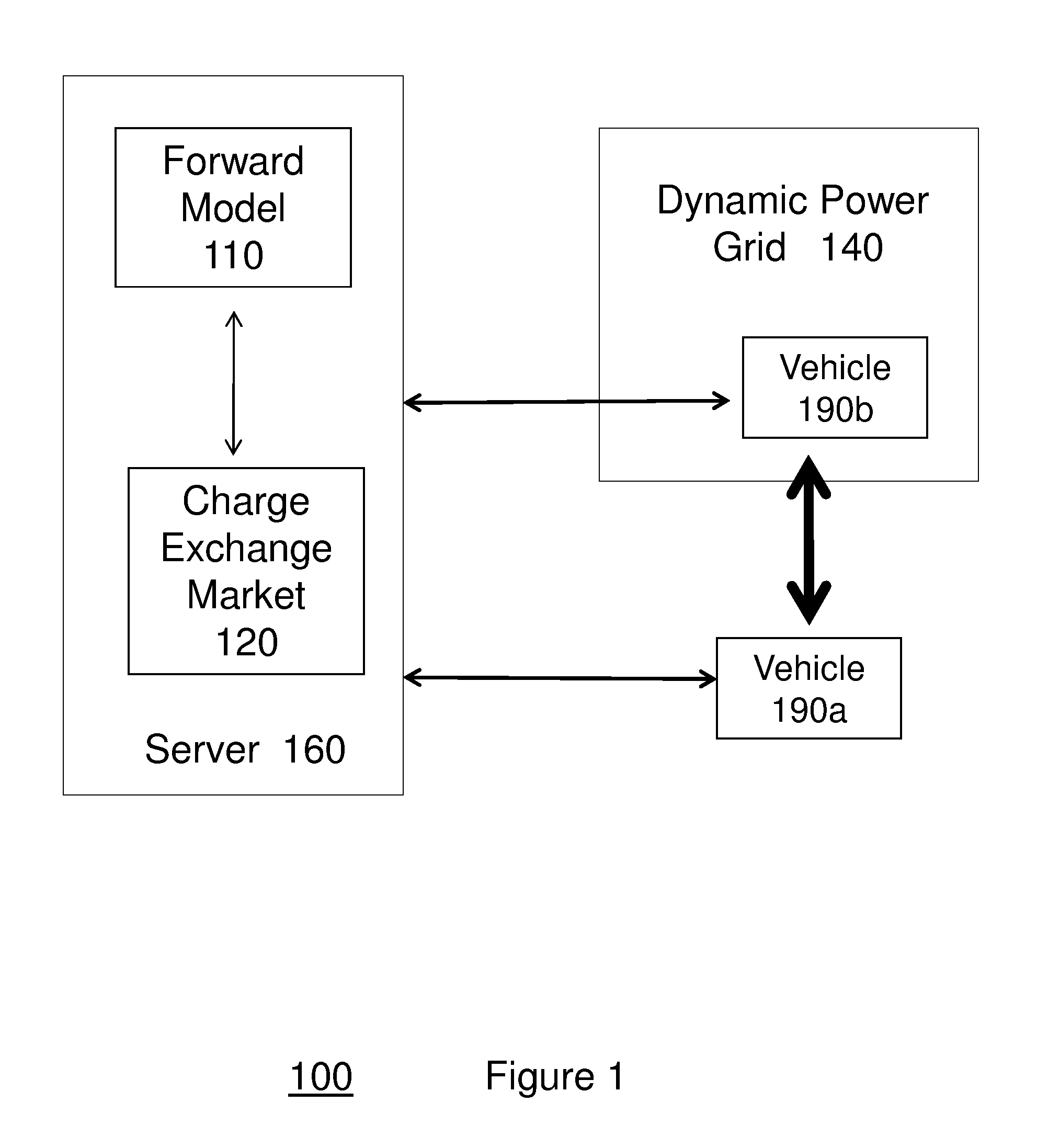
[0045]Conventional systems and methods do not exist to facilitate the formation of “Flash Charge Mobs,” in which vehicles congregate to exchange charge. In particular, conventional methods do not facilitate formation of Flash Charge Mobs in which an exchange of charge is optimally based on a forward model of vehicle power utilization, the creation of an ad hoc market for buying and selling spare charging capacity among vehicles underway, and / or a dynamically configured mini-grid for delivering charge between vehicles at a particular voltage and capacity (e.g., amp hours) as determined by the market clearinghouse.

[0046]New solutions are needed for at least two reasons. Firstly, it is well-known that electrical grid capacity must be sized to meet peak demands. Shifting demand from peak to non-peak hours thus aids both the utility provider specifically, as well as...


PUM


Abstract

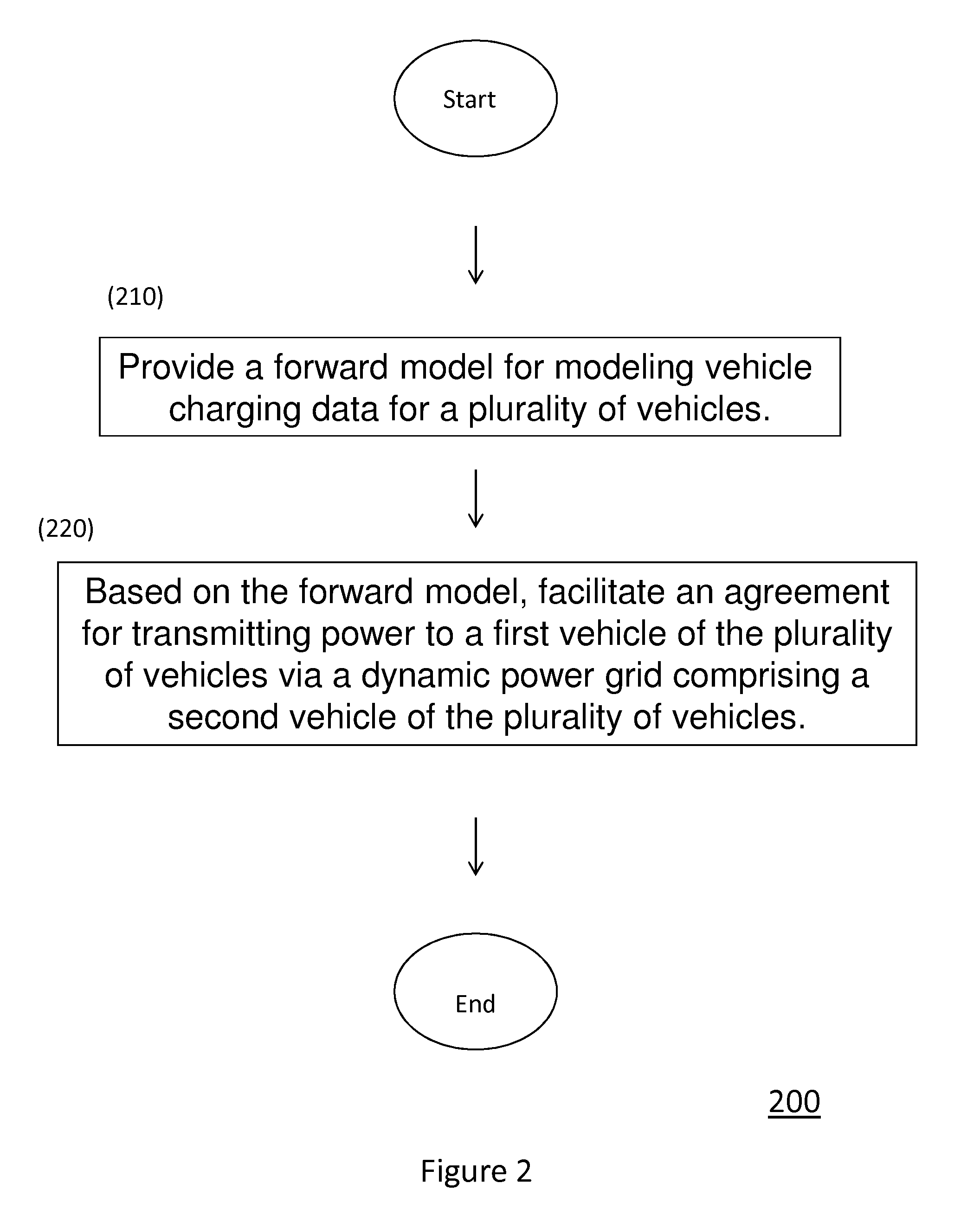
A system for charging a vehicle includes a forward model for modeling vehicle charging data for a plurality of vehicles, and a charge exchange market which, based on the forward model, facilitates an agreement for transmitting power to a first vehicle of the plurality of vehicles via a dynamic power grid including a second vehicle of the plurality of vehicles. A system of managing power consumption in the vehicle includes, an optimizing unit for optimizing a plurality of parameters to determine a power to be consumed by the vehicle based on a plurality of power source signatures for a plurality of power sources, and an operating mode setting unit for setting an operating mode for powering the vehicle based on the determined power.

Description

BACKGROUND OF THE INVENTION[0001]1. Field of the Invention[0002]The present invention relates to a system and method of charging a vehicle and a system and method of managing power consumption in a vehicle, and more particularly, a system and method of charging a vehicle using a dynamic power grid and a system and method of managing power consumption in a vehicle which optimizes a plurality of parameters based on a plurality of power source signatures for a plurality of power sources.[0003]2. Description of the Related ArtCharging a Vehicle[0004]Charging an electric vehicle on a power grid conventionally requires a tradeoff between the power delivery capacity of the grid and the desired charging times of all vehicles charging on the grid.[0005]Batteries in battery electric vehicles (BEVs) must be periodically recharged. Most commonly, these vehicles charge from the power grid (at home or using a street or shop charging station), which is in turn generated from a variety of domestic ...

Claims


Application Information

Patent Timeline
Patent Type & Authority Applications(United States)
IPC IPC(8): B60L11/00H02J7/00H02J7/02
CPCH02J3/008Y02T90/121H02J13/0013H02J2003/007B60L1/02B60L1/14B60L11/1824B60L11/1842B60L11/1848B60L11/1861B60L2230/16B60L2230/22B60L2230/24B60L2230/40B60L2240/12B60L2240/34B60L2240/622B60L2240/662B60L2240/667B60L2240/68B60L2240/70B60L2240/72B60L2240/80B60L2250/12B60L2250/14B60L2250/16B60L2260/52B60L2260/54B60L2270/12Y02T90/16G06Q30/08G06Q40/04Y02T10/7088Y02T10/7044Y02T10/7005Y02T10/705Y02T90/162Y02T90/163Y02T90/169Y02T90/14Y02T90/128Y04S10/126Y04S10/58Y04S30/14Y04S50/10Y02E60/721Y02B70/3216Y02B90/2607Y04S20/221Y04S40/12Y04S40/22Y02E60/76Y02T10/7291H02J7/0027B60L53/63B60L53/65B60L53/665B60L58/12B60L53/305B60L53/51B60L53/52B60L53/68B60L55/00H02J2203/20H02J13/00006Y02B70/30Y02B90/20Y02E60/00Y02T10/70Y02T10/7072Y02T10/72Y02T90/12Y02T90/167Y04S40/20H02J7/0024H02J7/007H02J2310/48H02J7/342H02J7/00034Y04S10/50G01C21/3469
Inventor O'CONNELL, BRIANHAMILTON, RICKKOZLOSKI, JAMES R.PICKOVER, CLIFF
Owner IBM CORP
Learn More