Fluid activated flow control apparatus

a flow control and fluid technology, applied in water supply installation, process and machine control, instruments, etc., can solve the problems of inability to expand the flow in the pipeline, difficult expansion of the fluid delivery coverage, and high cost, and add new pipe runs that have the added difficulty of trenching and cutting or circumventing pavement,

Inactive Publication Date: 2013-08-15
COLT IRRIGATION
View PDF12 Cites 17 Cited by
  • Summary
  • Abstract
  • Description
  • Claims
  • Application Information

AI Technical Summary

Benefits of technology

[0038]The output valve is provided with a flow control arm. The output valve is aligned with the servo valve.

Problems solved by technology

Thus, for any single fluid source the flow in a pipeline is not expandable beyond a given length or number of fluid delivery terminals such as a sprinkler head.
Thus, expansion of fluid delivery coverage is difficult, costly, and commonly involves addition of additional source controls and pipe.
Adding new pipe runs has the added difficulty of requiring costly trenching and cutting or circumventing pavement such as sidewalks, roads, driveways, and patios.
More importantly, should all the control circuits be utilized in the existing system, expansion will require addition of a new or additional timing mechanism further increasing the cost, maintenance, and difficulty of operating the system.
This adds significantly to the cost of expanding an existing irrigation system and results in increased maintenance needs.
This multiple control system is costly to purchase and install.
Further, expansion of the existing system requires additional trenching to install new electric lines to regulate new valve systems.
These devices suffer from numerous drawbacks including water hammering due to slow activation or deactivation of the output valves and difficult or absent timing adjustment.
Devices that provided timing adjustment required a difficult and awkward process of changing the cams within the mechanism, thus requiring shutting down the system and professional adjustment.
Installation of prior art water distribution systems requires replacing or removing existing valve systems and replacing them with a complicated control device.
The complexity of the prior art control devices requires precise manufacturing standards to ensure functionality and results in increased cost of purchase, operation, and maintenance, thus, increasing warranty replacement costs and detrimentally affecting customer goodwill.

Method used


Image

  • Fluid activated flow control apparatus
  • Fluid activated flow control apparatus
  • Fluid activated flow control apparatus

Examples


first example embodiment

[0322]The first example operating environment illustrates the irrigation of a field using a single actuator without manual labor or electrical power beyond the central pump and master valve, see FIG. 11.

[0323]FIG. 11 illustrates the operating environment of a first example fluid activated actuator system. The operating environment consists of a pressurized water source (e.g., a water pump) 11000. The pressurized water is delivered using conventional water transport methods including, for example PVC pipes, to a master valve 11100. The master valve 11100, for example, is a conventional diaphragm valve. Attached to the master valve 11100 is a conventional valve controller 11200. The valve controller actuates the master valve 11100 into a closed or open position based upon a user configurable timing schedule. When the master valve 11100 is actuated into the on / open position by the controller 11200, pressurized fluid is released from the water source 11000 into the main line 11300. In t...

second example embodiment

[0378]The second example operating environment, similar to the first example, illustrates the irrigation of a field using a single actuator without manual labor or electrical power beyond the central pump and master valve. In this example, as compared to the first example, the sequencing valve actuator is mounted in the solenoid position in one of the diaphragm valves in the operating system. This fluid activated actuator configuration reduces the number of parts in the system, is simpler to install, and requires no bore hole in the main line.

[0379]FIG. 39 illustrates the operating environment of a second example fluid activated actuator system. The operating environment consists of a pressurized water source (e.g., a water pump) 11000. The pressurized water is delivered using conventional water transport methods including, for example PVC pipes, to a master valve 11100. The master valve 11100, for example, is a conventional diaphragm valve. Attached to the master valve 11100 is a c...

third example embodiment

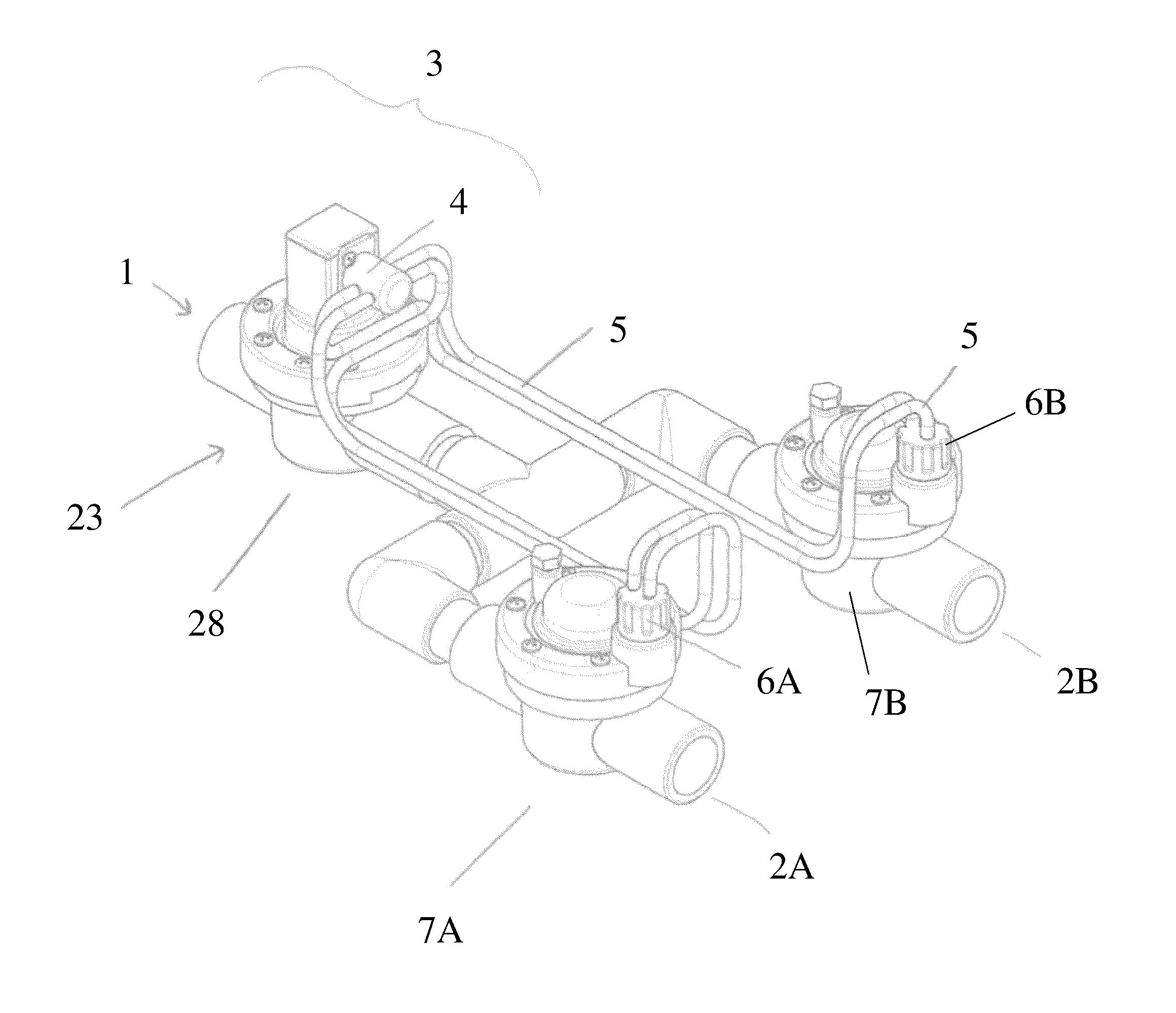
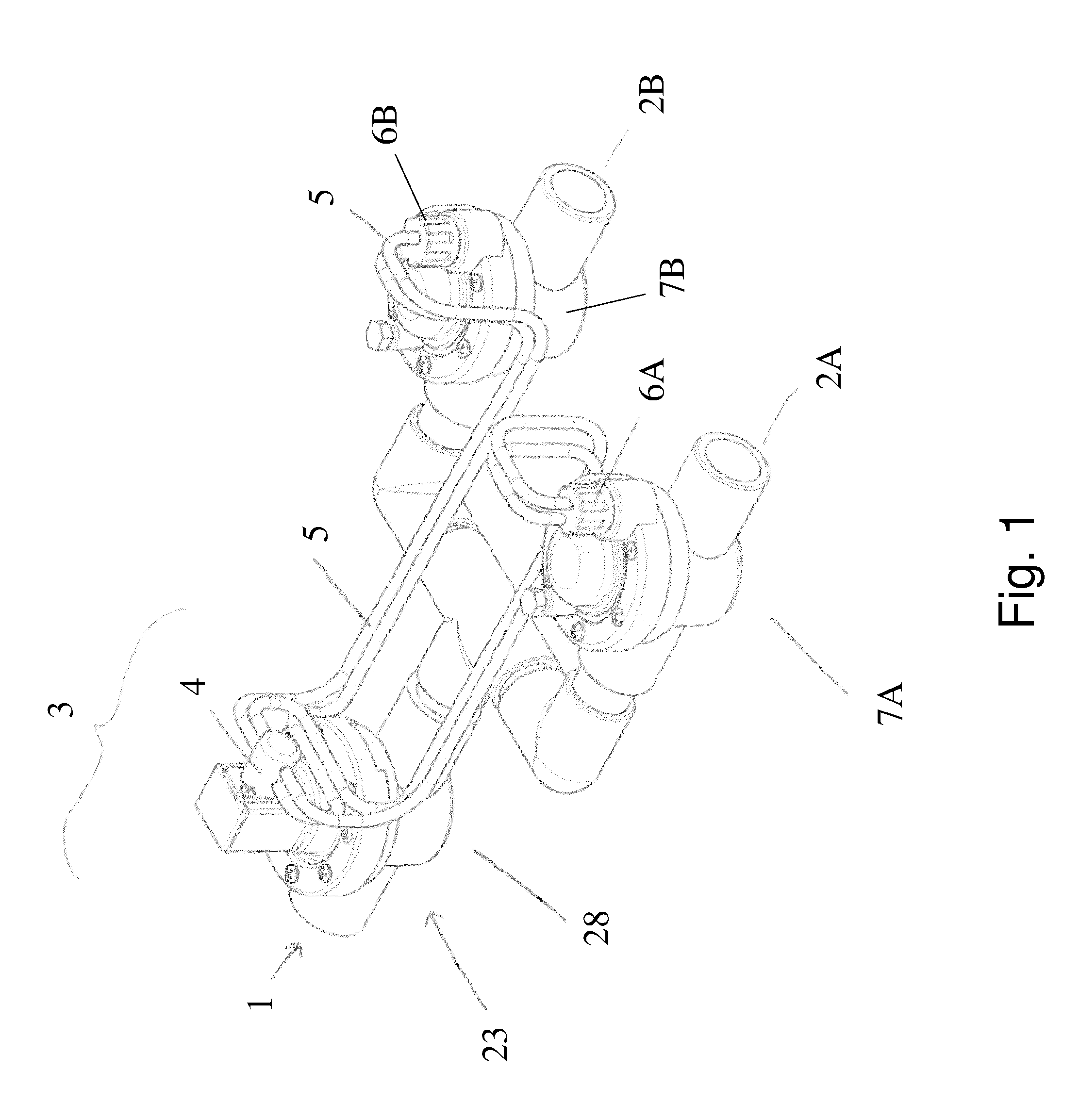
[0453]The third example operating environment, similar to the first and second example, illustrates the irrigation of a field using multiple fluid activated actuators without manual labor or electrical power beyond the central pump and master valve. In this example, as compared to the first and second example, the fluid activated valve actuator (labeled a lockstep actuator) is mounted in the solenoid position in each of the diaphragm valves in the operating system see FIG. 20 and FIG. 24. The lockstep actuator further simplifies the operating environment for a user but is designed using the same general concepts and principles as the actuators of examples 1 and 2. In particular, the lockstep actuators do not require connective tubing between the actuator and associated or slaved diaphragm valves.

[0454]FIG. 23 illustrates the operating environment of a third example fluid activated actuator system. The operating environment consists of a pressurized water source (e.g., a water pump) ...


PUM


Abstract

Embodiments of a fluid flow regulating device and methods of using the same are described. Certain embodiments manages fluid flow between one or more input ports and output ports at least partly in response to fluid pressure changes and/or by a mechanism driven by fluid flow, optionally without using electrical power.

Description

CROSS-REFERENCE TO RELATED APPLICATIONS[0001]This is a continuation-in-part of U.S. patent application Ser. No. 13 / 717,314 filed Dec. 17, 2012, which is a continuation-in-part of U.S. patent application Ser. No. 13 / 469,899 filed May 11, 2012, which is a continuation-in-part of U.S. patent application Ser. No. 12 / 028,992 filed Feb. 11, 2008, now U.S. Pat. No. 8,230,871, which claims priority from U.S. Provisional Application No. 60 / 901,055, Feb. 12, 2007, the contents of which are hereby incorporated by reference in their entirety.STATEMENT REGARDING FEDERALLY SPONSORED R&D[0002]Not applicable.REFERENCE TO SEQUENCE LISTING, TABLE, OR COMPUTER PROGRAM LISTING[0003]Not applicable.FIELD OF THE INVENTION[0004]This invention relates generally to devices and methods for regulating fluid flow and in particular, to pressure sensitive flow control apparatus and methods for using the same.BACKGROUND OF THE INVENTION[0005]Agricultural, commercial, and domestic irrigation systems are commonly co...

Claims


Application Information

Patent Timeline
Patent Type & Authority Applications(United States)
IPC IPC(8): F16K31/385
CPCF16K31/385G05D7/03Y10T137/7793Y10T137/268Y10T137/0379G05D7/018F16K11/22G05D7/012
Inventor HURST, JAMES WALTER
Owner COLT IRRIGATION
Why Eureka
Try Eureka