
Humidity detection sensor and a method for manufacturing the same

a technology of humidity sensing film and humidity sensor, which is applied in the direction of resistance/reactance/impedence, instruments, material analysis, etc., can solve the problems of upper electrode, inability to supply external water molecules smoothly to the humidity sensing film, and inability to achieve smooth supply of external water molecules, so as to improve the humidity resistance of the upper electrode

Active Publication Date: 2013-08-15
ALPS ALPINE CO LTD
View PDF8 Cites 14 Cited by
  • Summary
  • Abstract
  • Description
  • Claims
  • Application Information

AI Technical Summary

Benefits of technology

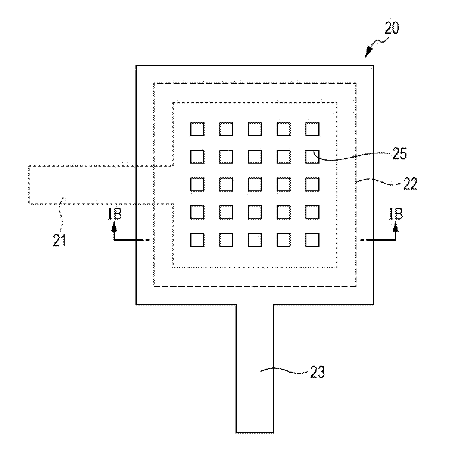
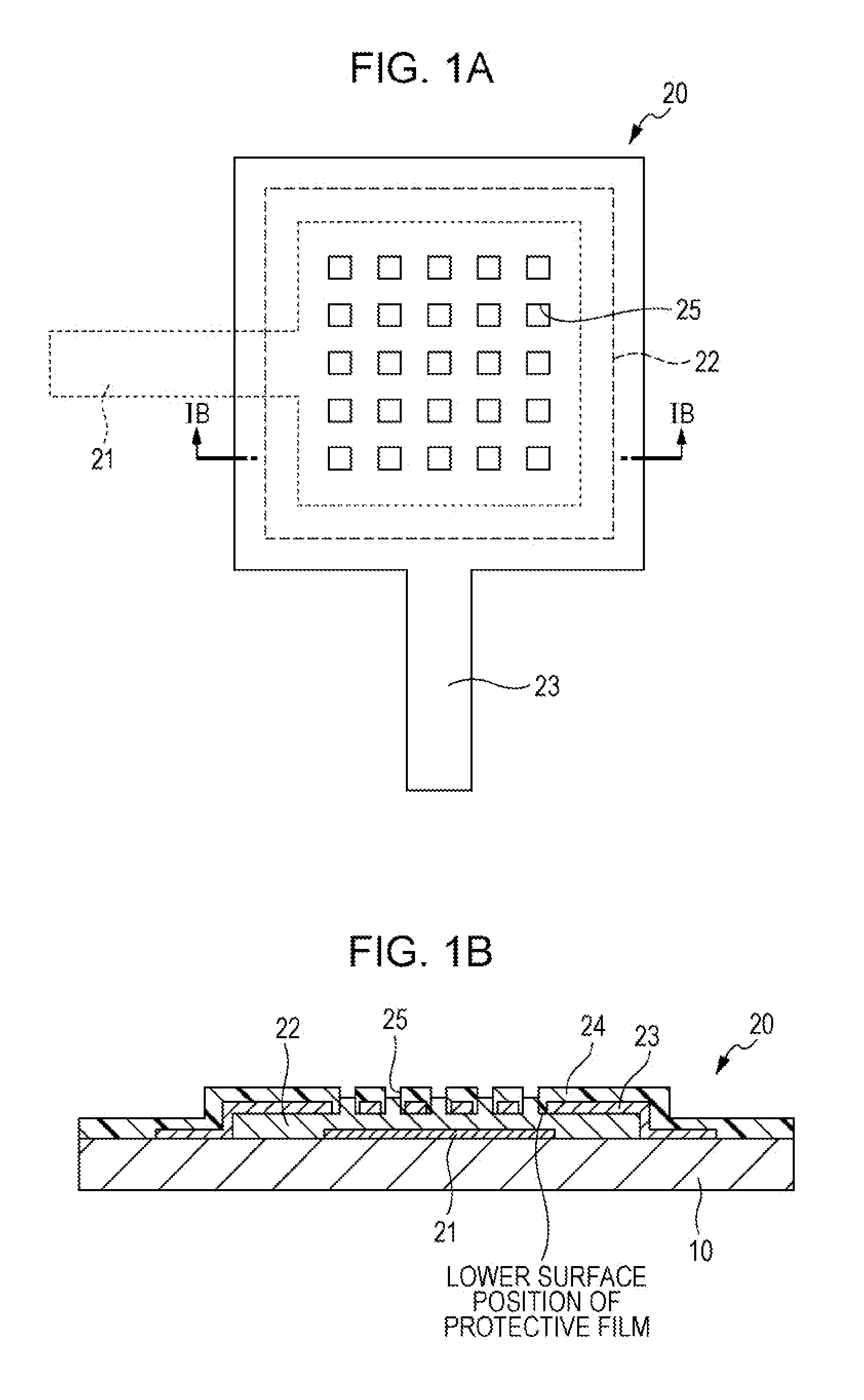
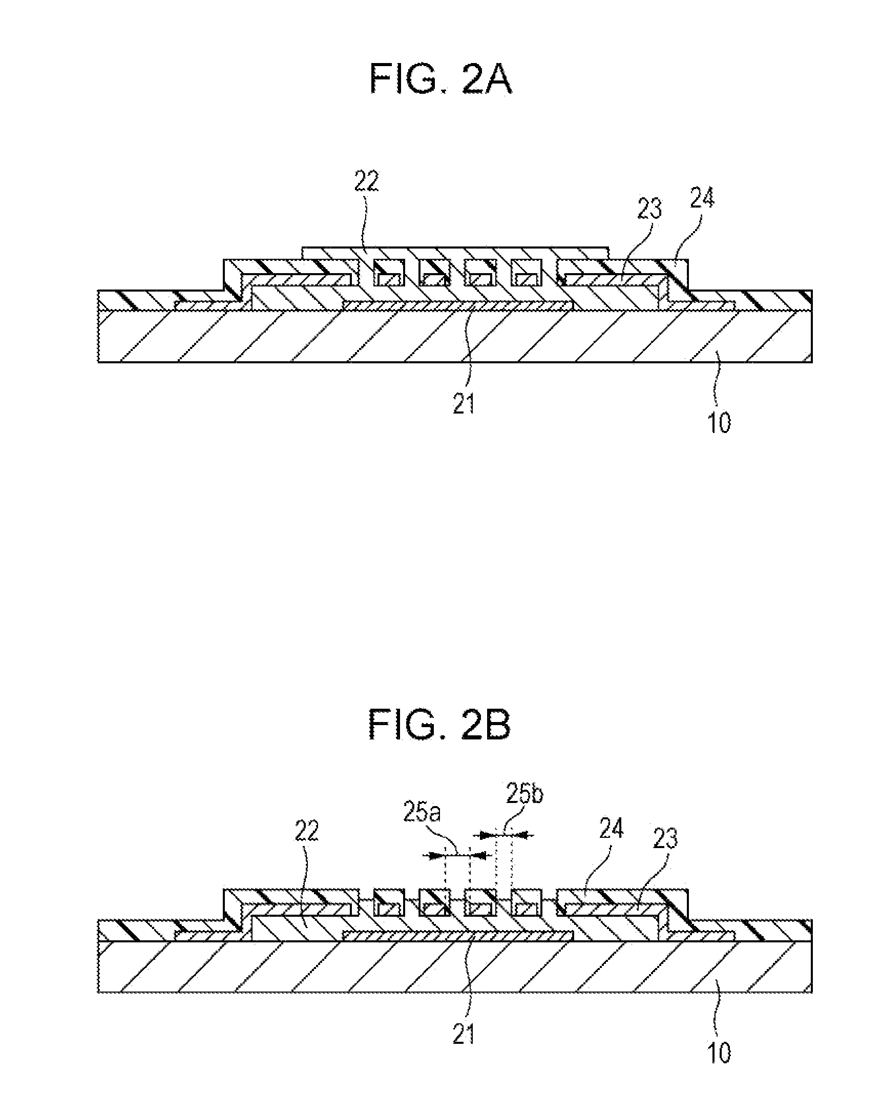
The present invention provides a humidity detection sensor with a structure that allows for smooth supply of external water molecules to the humidity sensing film and improved humidity resistance of the upper electrode. This is achieved without exposing the interface between the protective film and the humidity sensing film to external elements, reducing the entry of water molecules or corrosion components. The smooth supply of external water molecules allows for effective improvement of humidity resistance of the upper electrode.

Problems solved by technology

Meanwhile, in the case of the parallel-plate structure in which the humidity sensing film is interposed between the upper and lower electrodes, the upper electrode is exposed, and thus a problem of humidity resistance, such as corrosion of the upper electrode due to water or the like, arises.
However, as described in PCT Japanese Translation Patent Publication No. 2003-516538, in the parallel-plate structure in which the humidity sensing film is provided between the upper and lower electrodes, when the upper electrode is partially removed to partially expose the humidity sensing film, thereby smoothly supplying water molecules to the humidity sensing film, if a protective film is formed over the entire surface, external water molecules cannot smoothly be supplied to the humidity sensing film.
However, in this case, a problem of corrosion from side surfaces of the exposed upper electrode is considered.

Method used


Image

  • Humidity detection sensor and a method for manufacturing the same
  • Humidity detection sensor and a method for manufacturing the same
  • Humidity detection sensor and a method for manufacturing the same

Examples


Embodiment Construction

[0026]The present inventors have focused on a structure in which, when a sensor section of a humidity detection sensor is configured to have a parallel-plate structure in which a humidity sensing film is interposed between upper and lower electrodes, a protective film for blocking exchange of water with the outside is provided on the upper electrode. When the structure is provided in which the humidity sensing film is interposed between the upper and lower electrodes, in order to allow water molecules to smoothly pass to the inside of the humidity sensing film, it is necessary to partially remove the protective film and the electrode formed on the humidity sensing film, thereby exposing the humidity sensing film of the sensor section to the outside. As a method for this, a method is conceivable in which an upper electrode having openings is formed on the humidity sensing film, and then a protective film is formed so as to cover the upper electrode and is partially removed by a dry e...


PUM

PropertyMeasurementUnit
capacitanceaaaaaaaaaa
humidityaaaaaaaaaa
dielectric constantaaaaaaaaaa

Abstract

A humidity detection sensor includes a lower electrode provided on a board, an upper electrode provided so as to face the lower electrode, a humidity sensing film which is formed at least between the lower electrode and the upper electrode and whose dielectric constant changes in response to humidity, and a protective film provided so as to cover the upper electrode. Each of the upper electrode and the protective film has an opening through which the humidity sensing film is partially exposed to the outside. In the opening, the humidity sensing film is provided so as to reach at least a position higher than the position of the lower surface of the protective film.

Description

CLAIM OF PRIORITY[0001]This application is a Continuation of International Application No. PCT / JP2011 / 068082 filed on Aug. 8, 2011, which claims benefit of Japanese Patent Application No. 2010-224660 filed on Oct. 4, 2010. The entire contents of each application noted above are hereby incorporated by reference.BACKGROUND OF THE INVENTION[0002]1. Field of the Invention[0003]The present invention relates to a humidity detection sensor including a dielectric substance as a humidity sensing film and a method for manufacturing the same.[0004]2. Description of the Related Art[0005]As a humidity detection sensor used for measuring a humidity change, there is a capacitance type humidity detection sensor including a dielectric substance as a polymer humidity sensing film whose dielectric constant changes in response to an amount of absorbed or discharged water. The capacitance type humidity detection sensor includes a sensor section whose capacitance changes in response to humidity; and a re...

Claims


Application Information

Patent Timeline
Patent Type & Authority Applications(United States)
IPC IPC(8): G01N27/22
CPCY10T29/49G01N27/223G01N1/00G01N2201/00H01L21/00
Inventor TONDOKORO, ATSUSHIWAGA, SATOSHISATO, TAKASHIYOKOYAMA, SHINYAMORITA, SUMIHITO
Owner ALPS ALPINE CO LTD
Learn More