Backside covering material for a solar cell module and its use

Inactive Publication Date: 2002-09-19
BRIDGESTONE CORP
View PDF0 Cites 58 Cited by
  • Summary
  • Abstract
  • Description
  • Claims
  • Application Information

AI Technical Summary

Benefits of technology

0009] An object of this invention is to provide a backside covering material for a rear surface protection member of a solar cell module which doesn't have any disadvantages mentioned above, is light and thin, has improved moisture r

Problems solved by technology

However, there are several disadvantages associated with the conventional backside covering material using metal foil.
First, a solar cell module using the conventional material sometimes has leak current.
Second, projections of und

Method used


Image

  • Backside covering material for a solar cell module and its use
  • Backside covering material for a solar cell module and its use
  • Backside covering material for a solar cell module and its use

Examples


examples 1 and 2

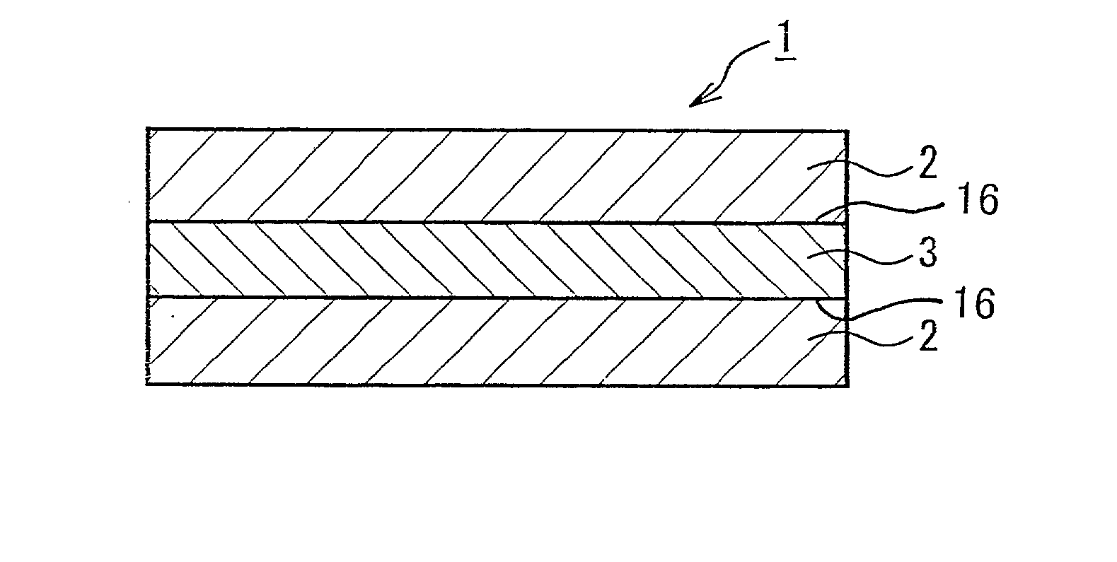
[0061] One of two films having heat resistance and weather resistance was made of polyester film mixed with a white pigment (U2, manufactured by Teijin-Du Pont Film, Co. Ltd., thickness: 38 .mu.m) and the other film was made of ETFE film (AFFLEX manufactured by Asahi Glass Co. Ltd., thickness: 21 .mu.m). After placing a moisture resistant film having a composition in Table 1 in between two films described above, those three films were bonded to make a backside covering material of this invention. The bonding was done through an ordinary dry lamination method at temperature 60-90.degree. C. with 3 kg of nip pressure using an acrylic urethane adhesive applied with 10 .mu.m of thickness.

[0062] The backside covering materials made by the method described above have been through the endurance test, in which the materials were let stand for 1000 hours under a more harsh condition, at 85.degree. C. with 90% RH, than an ordinary endurance test condition, at 65.degree. C. with 95% RH. After ...

example 3

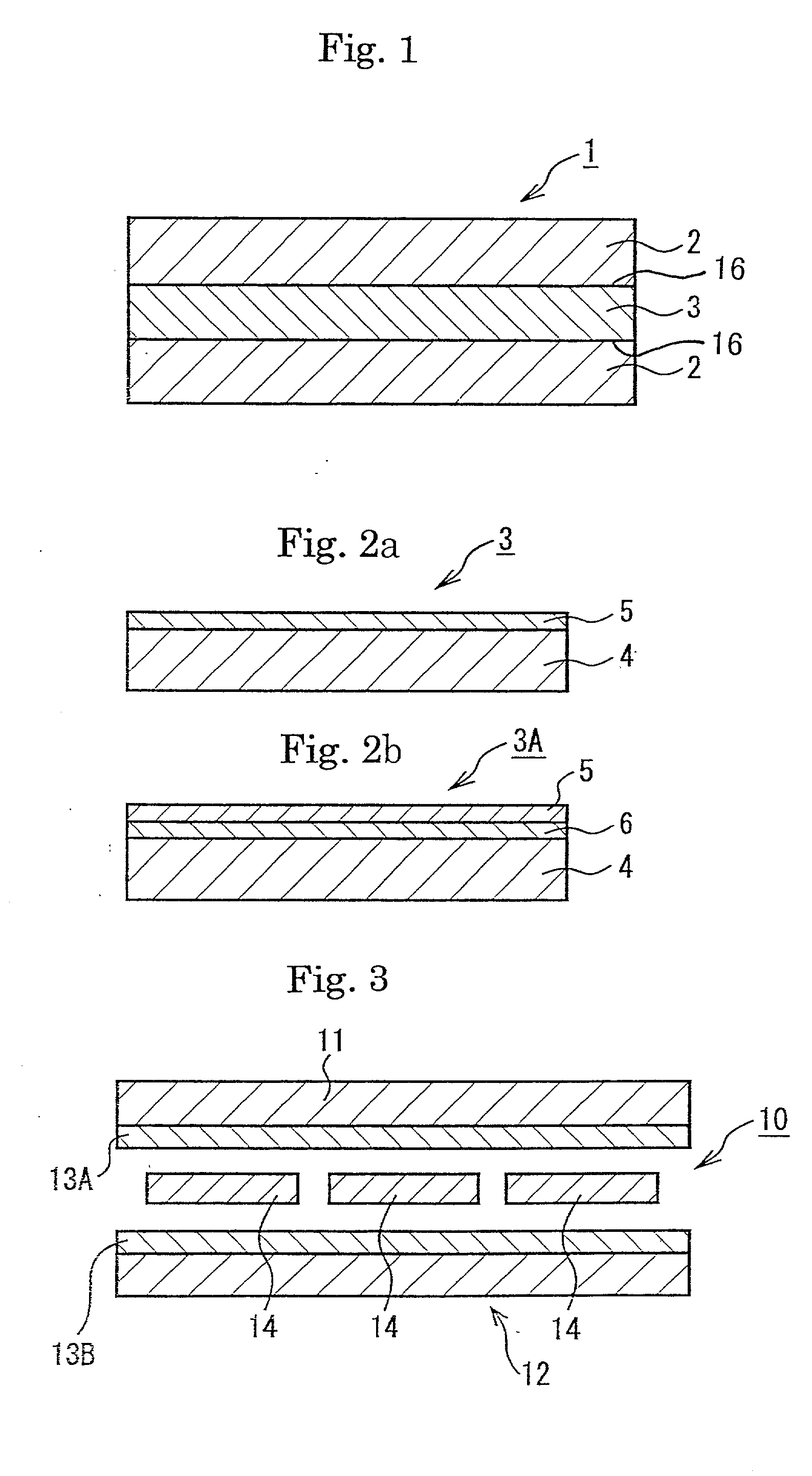
[0065] One of two films having heat resistance and weather resistance was made of polyester film mixed with a white pigment (U2 manufactured by Teijin-Du Pont Film, Co. Ltd., thickness: 38 .mu.m) and the other film was made of ETFE film (AFFLEX manufactured by Asahi Glass, Co. Ltd., thickness: 21 .mu.m). A moisture resistant film was made by depositing SiOx (x=1.8) on a surface of PET film with 12 .mu.m of thickness to form a moisture resistance layer with 200 .ANG. of thickness. The moisture resistant film was placed in between two films having heat resistance and weather resistance. These three films were bonded with an adhesive given in Table 2. Further EVA adhesive layer with 50 .mu.m of thickness was formed on the outer surface of the polyester film to make a backside covering material working also as a sealant of this invention.

[0066] The obtained backside covering material unified with the sealant has been through an endurance test, in which the material was let stand for 100...


PUM

PropertyMeasurementUnit
Linear densityaaaaaaaaaa
Lengthaaaaaaaaaa
Lengthaaaaaaaaaa

Abstract

The present invention provides a light and thin backside covering material for a solar cell module which is excellent in moisture resistance and durability and has a good insulator without causing a short circuit with underlying wire nor leak current. Also the invention provides a durable and high performance solar cell module using this backside covering material as a rear surface protection member. The backside covering material for a solar cell module is a three-layer laminated film, wherein a moisture resistant film is sandwiched with two films having heat resistance and weather resistance. A deposited layer 5 of inorganic oxide is formed on a surface of a base film 4 to make the moisture resistant film 3.

Description

CROSS REFERENCE TO RELATED APPLICATION[0001] This is a continuation application of PCT / JP01 / 04832 filed on Jun. 8, 2001.FIELD OF THE INVENTION[0002] The present invention relates to a backside covering material used for a rear surface protection member of a solar cell module and a solar cell module using said material. Particularly, it relates to the backside covering material for a solar cell module having excellent moisture resistance and durability and insulating very well to prevent leak current, and to a durable and high-performance solar cell module using the material as the rear surface protection member.BACKGROUND OF THE INVENTION[0003] A solar cell module has been paid attention as a device directly converting solar energy into electric energy from the aspects of effective use of natural resources and ecology, and various solar cell modules have been developed.[0004] As shown in FIG. 3, in a solar cell module, solar cells 14 (photovoltaic element made of silicon etc.) are s...

Claims


Application Information

Patent Timeline
IPC IPC(8): H01L31/042H01L31/048
CPCB32B17/10788Y02E10/50Y10T428/31855Y10T428/3154H01L31/049C09J7/29Y10T428/24959Y10T428/31725Y10T428/31544Y10T428/31623Y10T428/24975Y10T428/2495Y10T428/31616B32B27/00B32B2307/7246B32B27/36B32B27/365B32B2307/732B32B2307/712B32B2307/206B32B2255/20B32B2457/12B32B27/34B32B2255/26B32B2250/24B32B27/322B32B2307/306B32B2307/748B32B2255/10B32B7/12B32B27/308B32B27/304B32B2255/28B32B2250/03B32B27/08
Inventor MIURA, TERUOAKUZAWA, KAZUYOSHIMORIMURA, YASUHIRO
Owner BRIDGESTONE CORP
Why Eureka
Try Eureka