Explosion-protected fuel cell

a fuel cell and explosion-protective technology, applied in the direction of fuel cell auxilaries, fuel cells, electrochemical generators, etc., to achieve the effect of more reliable and safe us

Inactive Publication Date: 2013-08-15
R STAHL SCHALTGERATE +1
View PDF3 Cites 5 Cited by
  • Summary
  • Abstract
  • Description
  • Claims
  • Application Information

AI Technical Summary

Benefits of technology

[0008]It is an object of the present invention to provide a fuel cell arrangement that is adapted for more reliable and safe usage in explosion-prone environments. The inventive fuel cell arrangement comprises a fuel cell stack with at least one inlet for an oxidizing agent, at least one inlet for a reducing agent (i.e. fuel), at least one outlet for reaction products and / or residual gases, and at least two electric terminals. The fuel cell stack preferably comprises several individual fuel cells that are connected to the respective inlets and outlets via a corresponding distributor and connected to the electric terminals. The oxidizing agent consists, for example, of air or oxygen. The reducing agent consists of hydrogen or another fuel.

Problems solved by technology

However, the latter requires separation from the cooling circuit.

Method used


Image

  • Explosion-protected fuel cell
  • Explosion-protected fuel cell
  • Explosion-protected fuel cell

Examples


Embodiment Construction

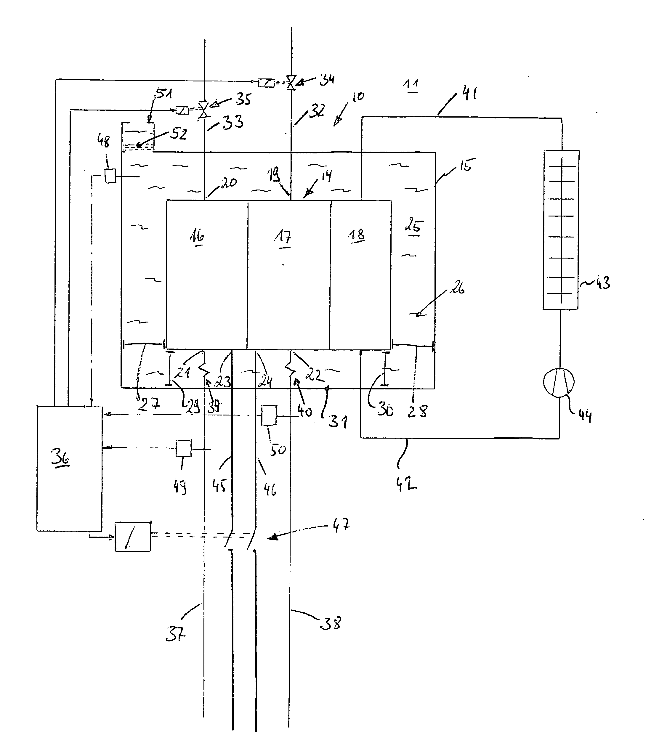
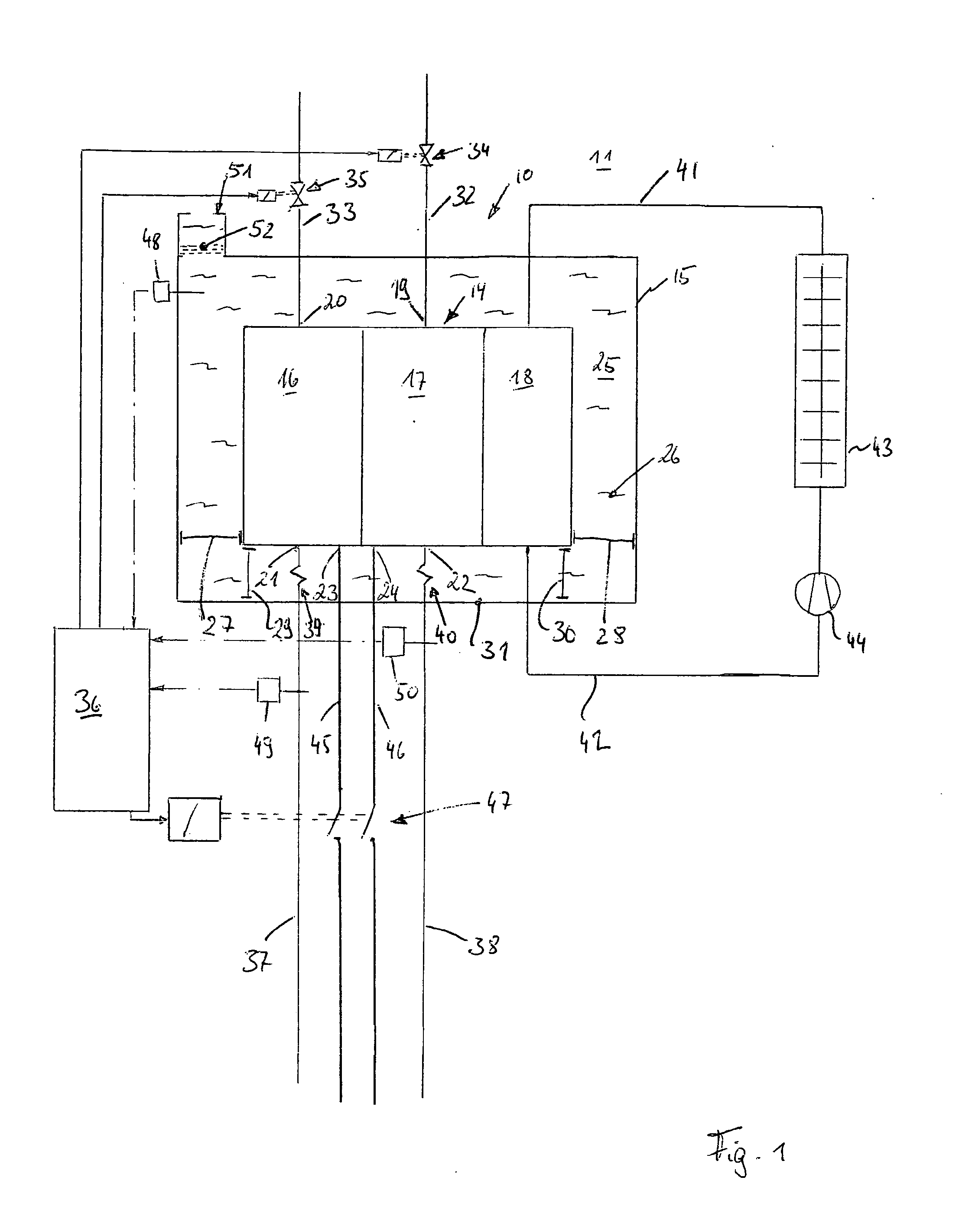
[0025]Referring more particularly to FIG. 1 of the drawings, there is shown an illustrative fuel cell arrangement 10 in accordance with the invention arranged in an explosion-prone environment 11. The fuel cell arrangement 10 forms part of a system that is constructed in an explosion-proof fashion and which additionally comprises other components such as coolers and fans, compressors, an accumulator, sensors and actuators, as well as a control, all of which are preferably also arranged in an explosion-proof fashion.

[0026]The centerpiece of the fuel cell arrangement 10 is a fuel cell stack 14 and a containment housing 15 that encloses this fuel cell stack on at least five sides. The fuel cell stack 14 comprises several fuel cells, preferably many individual fuel cells, that are combined into what is commonly referred to as a “stack”. Each individual fuel cell comprises an anode, a cathode, a solid or liquid electrolyte arranged in between or, for example, a proton-exchange membrane, ...


PUM

PropertyMeasurementUnit
heat storage capacityaaaaaaaaaa
thermal conductivityaaaaaaaaaa
temperatureaaaaaaaaaa

Abstract

A fuel cell arrangement operable in environments that are prone to explosions including a fuel cell stack 14 that is housed in a containment vessel 15 filled with a heat equalizing fluid 26 and provided with a cooling system. The heat equalizing fluid 26 flows around all sides of the fuel cell stack 14 and prevents a direct concentrated heat transfer from the surface of the fuel cell stack 14 to the containment housing 15. The heat equalizing fluid 26 buffers and distributes local heat peaks originating from the fuel cell stack 14 and thus eliminates ignition sources.

Description

FIELD OF THE INVENTION[0001]The invention relates to fuel cell arrangements for use in environments that are prone to explosions.BACKGROUND OF THE INVENTION[0002]Fuel cells are known for generating electric energy by oxidizing a suitable fuel, i.e., a reducing agent, such as, for example, hydrogen with air or oxygen. Waste heat is generated during the normal operation of the fuel cell. The waste heat typically is generated on individual elements such as, for example, the electrodes of a proton-exchange membrane or on other elements. Cooling systems are frequently utilized for the dissipation of the waste heat.[0003]Atypical operating modes and faults or damage of the fuel cell may cause a local temperature rise on the fuel cell that cannot be sufficiently suppressed by an industrial cooling system. For example, the fuel cell or parts thereof may heat up at locations that come in contact with the explosive ambient atmosphere. One particular problem with respect to explosion protectio...

Claims


Application Information

Patent Timeline
Patent Type & Authority Applications(United States)
IPC IPC(8): H01M8/04
CPCH01M8/04029H01M8/04052H01M8/04343Y02E60/50H01M8/04358H01M8/04679H01M8/2475H01M8/0435
Inventor HORN, THOMASJOHANNSMEYER, ULRICHSCHIMMELE, ANTON
Owner R STAHL SCHALTGERATE
Why Eureka
Try Eureka