Connector and fuel cell

Active Publication Date: 2013-08-15
TOYOTA JIDOSHA KK
View PDF2 Cites 7 Cited by
  • Summary
  • Abstract
  • Description
  • Claims
  • Application Information

AI Technical Summary

Benefits of technology

The present invention aims to solve issues with connectors and fuel cells by introducing guide members that improve connection with the fuel cell. These guide members are formed in the connector and clamp the separator, ensuring secure connection and reducing the likelihood of failure, such as bad connection or damage. Overall, this invention provides a more efficient and reliable connection between connectors and fuel cells.

Problems solved by technology

When the connector is connected with the fuel cell, displacement of the insertion direction of the connector to the fuel cell or misalignment of the insertion position of the connector to the fuel cell may cause bad connection or damage of the fuel cell.

Method used


Image

  • Connector and fuel cell
  • Connector and fuel cell
  • Connector and fuel cell

Examples


first embodiment

A. First Embodiment

A-1. External Configuration of Connector

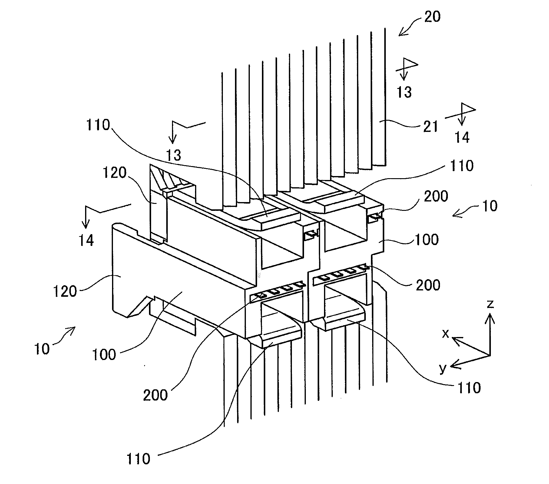
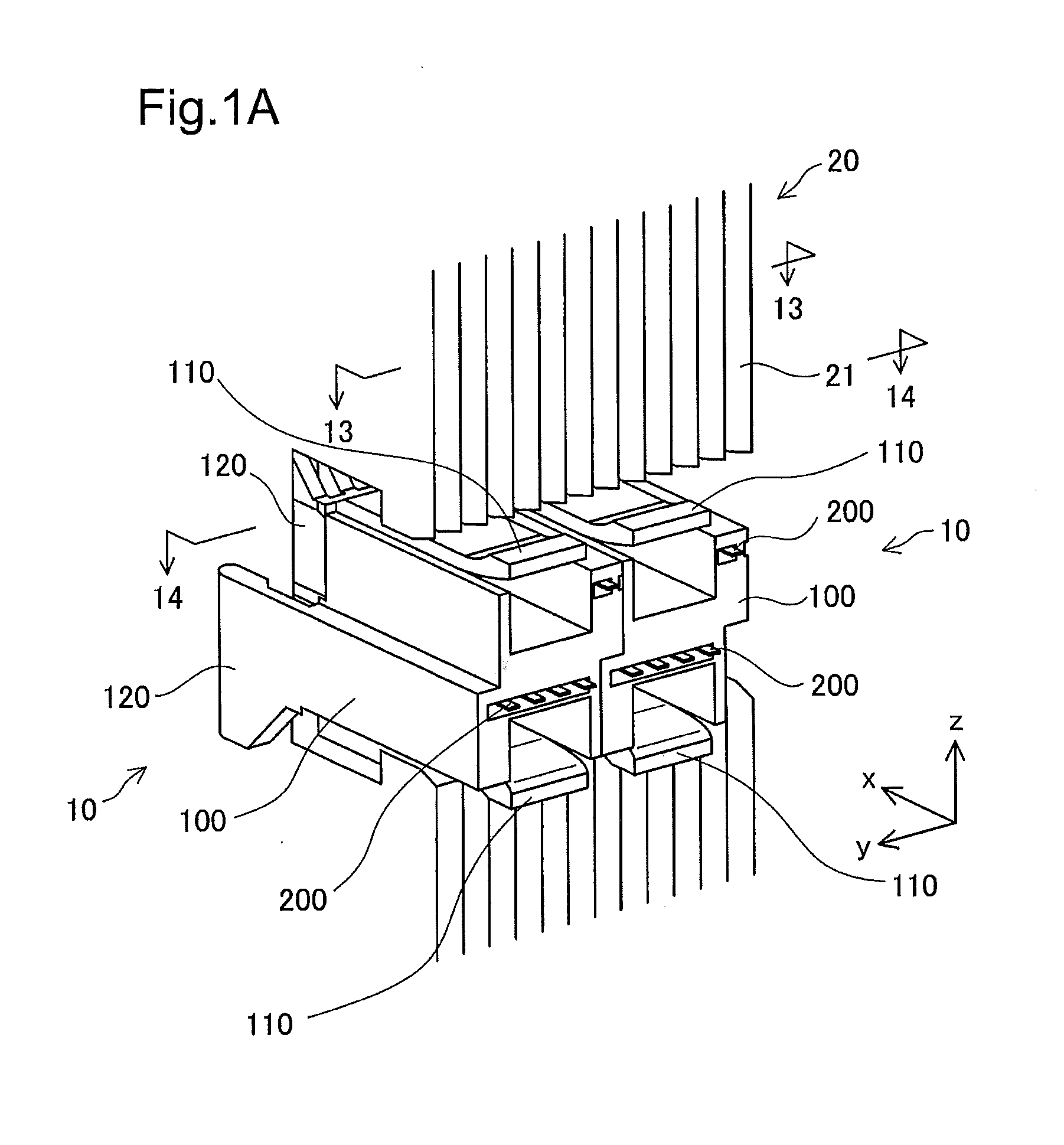
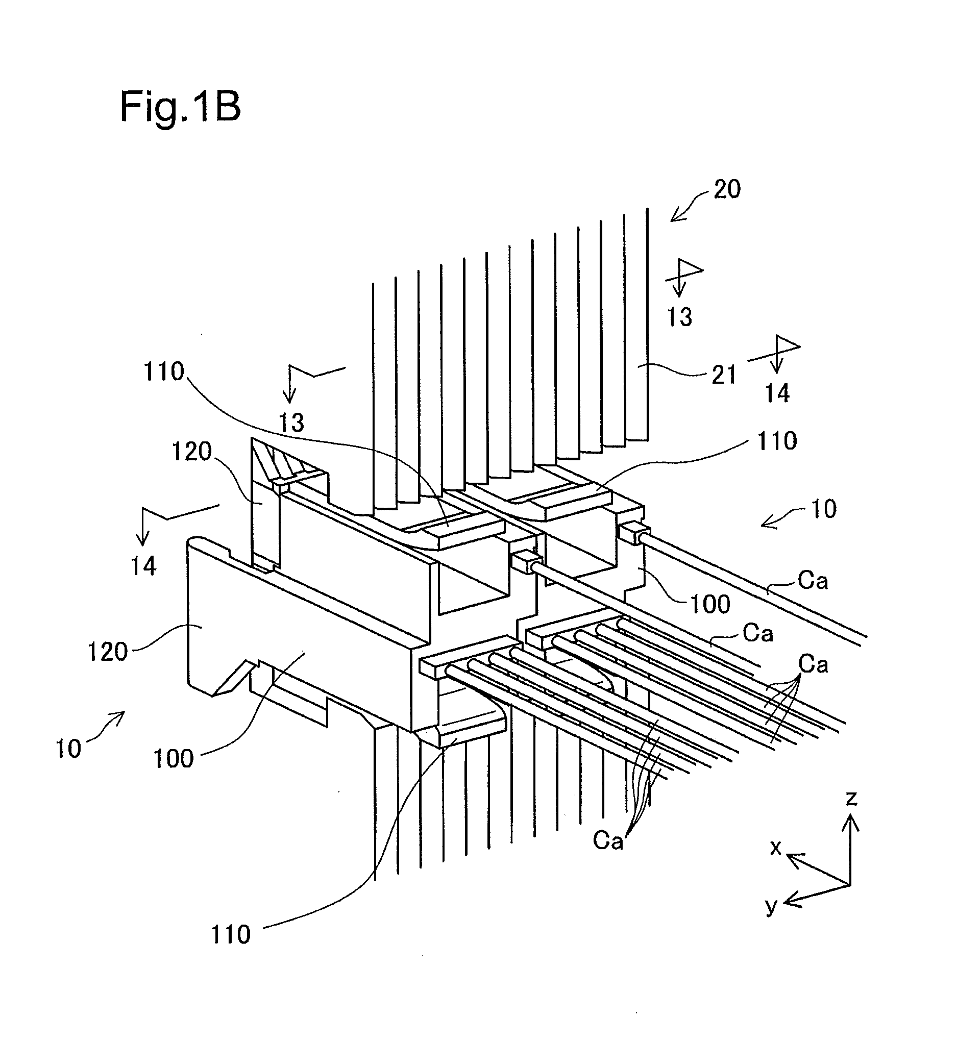
[0038]FIG. 1A illustrates the state that connectors according to a first embodiment of the invention are attached to a fuel cell. FIG. 1B illustrates the state that cables are connected to the connectors according to the first embodiment of the invention. FIG. 2 illustrates the external configuration of the connector according to the first embodiment of the invention. The connector 10 is used to connect detectors (not shown) for detecting voltages with the fuel cell 20 via the cables Ca and is attached to separators 21 of the fuel cell 20 to be electrically connected with the fuel cell 20. FIGS. 1A and 1B (hereinafter collectively referred to as FIG. 1) illustrate the state that two connectors 10 are attached to the separators 21. The connector 10 includes a connector casing 100 made of a resin and formed in a box-like shape and terminals 200 made of a conductive material and held by the connector casing 100.

[0039]According ...


PUM


Abstract

A connector is connected with a connector joint structure formed in separators in a fuel cell. The connector has: a connector casing; a terminal element that is provided in the connector casing and is configured to be in contact with an edge side of the separator and to be elastically deformed in an insertion direction of the connector that is orthogonal to a stacking direction of the separators, when the connector is connected with the connector joint structure; and an engagement element that is formed in the connector casing and is configured to engage with the connector joint structure and restrict motion of the connector in the insertion direction when the connector is connected with the connector joint structure.

Description

TECHNICAL FIELD[0001]The present invention relates to a connector and a fuel cell.BACKGROUND ART[0002]As is conventionally known, a connector is attached to, for example, separators of a fuel cell to detect the voltage of power generation by respective cells of the fuel cell. When the connector is connected with the fuel cell, displacement of the insertion direction of the connector to the fuel cell or misalignment of the insertion position of the connector to the fuel cell may cause bad connection or damage of the fuel cell. In order to solve this problem, one proposed technique provides a protruded guide member on one of the connector and the fuel cell and a recessed groove on the other of the connector and the fuel cell and slides the connector to be connected with the fuel cell while the guide member is fit in the groove (PTL1).CITATION LISTPatent Literatures[0003]PTL1: JP 2007-200633A[0004]PTL2: JP 2004-79195A[0005]PTL3 JP 2007-280872A[0006]PTL4: JP 2007-87858A[0007]PTL5: JP 20...

Claims


Application Information

Patent Timeline
IPC IPC(8): H01M8/02
CPCH01M8/0297H01M2008/1095H01R13/2442H01M8/0202H01R24/62Y02E60/50H01R13/6273H01M8/241H01M8/2457
Inventor OTAKE, YASUKIFUJITA, HIROSHI
Owner TOYOTA JIDOSHA KK
Why Eureka
Try Eureka