
MINIMAL POWER LATCH FOR SINGLE-SLOPE ADCs

a technology of adcs and latches, applied in the field of electronic circuits, can solve problems such as crosstalk or linearity, and achieve the effect of a minimal power latch circui

Active Publication Date: 2013-08-22
CALIFORNIA INST OF TECH
View PDF4 Cites 3 Cited by
  • Summary
  • Abstract
  • Description
  • Claims
  • Application Information

AI Technical Summary

Benefits of technology

The invention is a minimal power latch circuit for measuring signals. It consists of two latches that operate according to a pair of equations. The circuit receives a comparator signal, a code value signal, and a signal to be measured. The comparator signal is generated by comparing the signal to be measured with a reference signal that is generated by a monotonically varying reference signal. The circuit is designed to operate with low power and can be used in a variety of applications such as measuring signals from an M×N array of sources. The technical effects of the invention include improved accuracy and efficiency in measuring signals with low power consumption.

Problems solved by technology

However, in both these circuits the internal nodes switch every time the code changes until the comparator trips and freezes the value.
The instantaneous current, multiplied by the number of columns, can be quite large and it will contain very high frequency components which can create noise.
This changing power supply loading may lead to crosstalk or linearity issues.

Method used


Image

  • MINIMAL POWER LATCH FOR SINGLE-SLOPE ADCs
  • MINIMAL POWER LATCH FOR SINGLE-SLOPE ADCs
  • MINIMAL POWER LATCH FOR SINGLE-SLOPE ADCs

Examples


Embodiment Construction

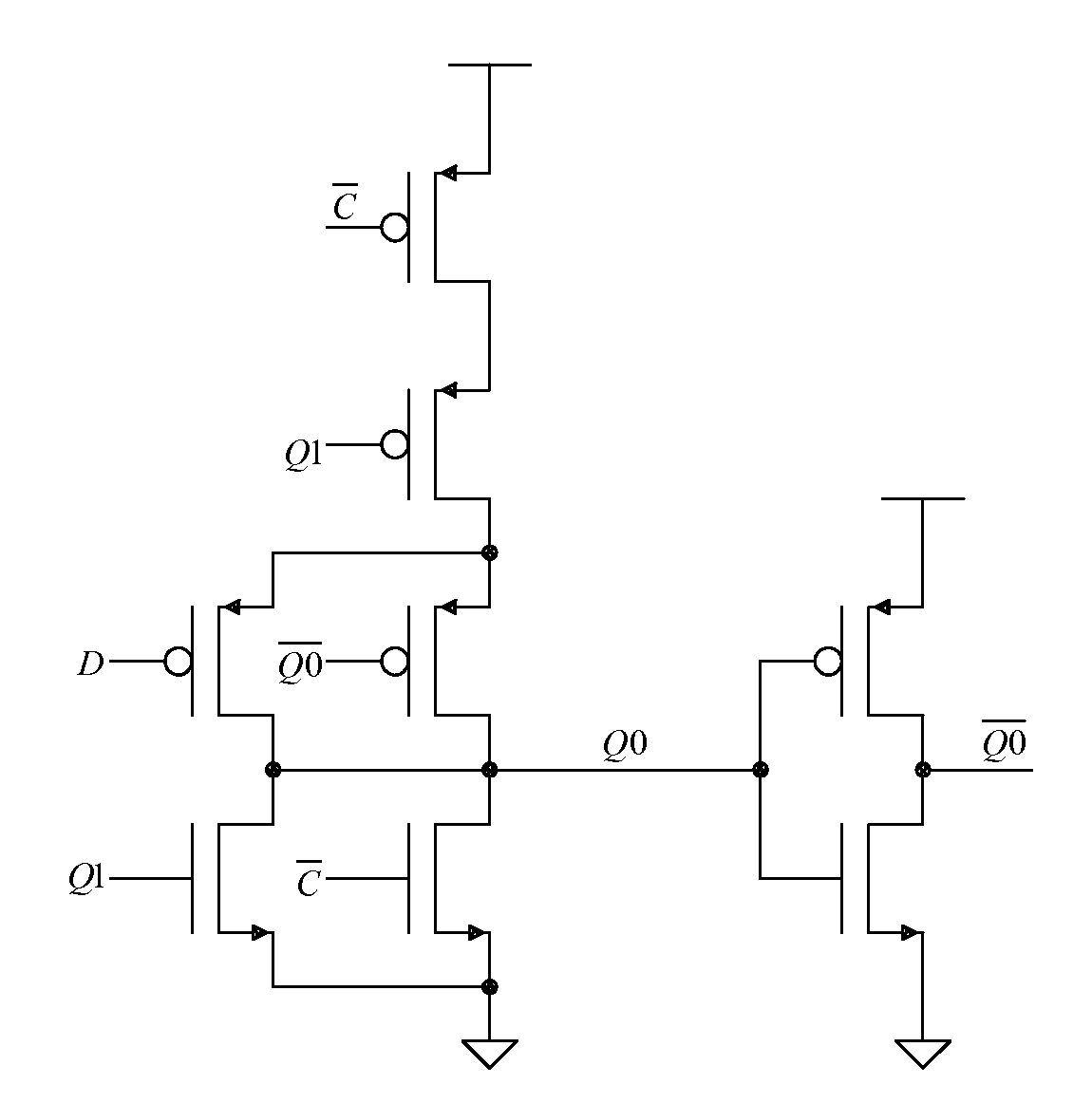
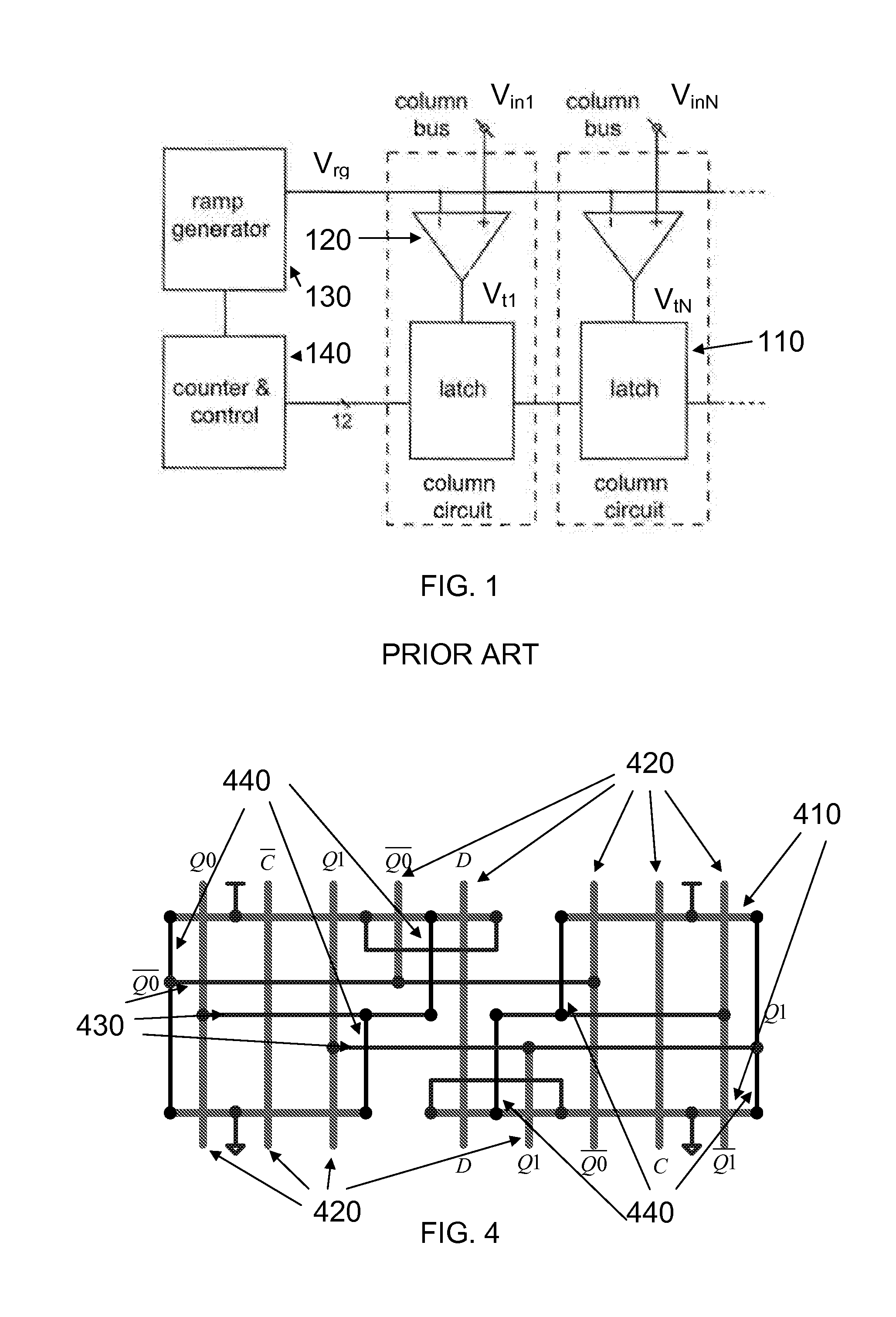
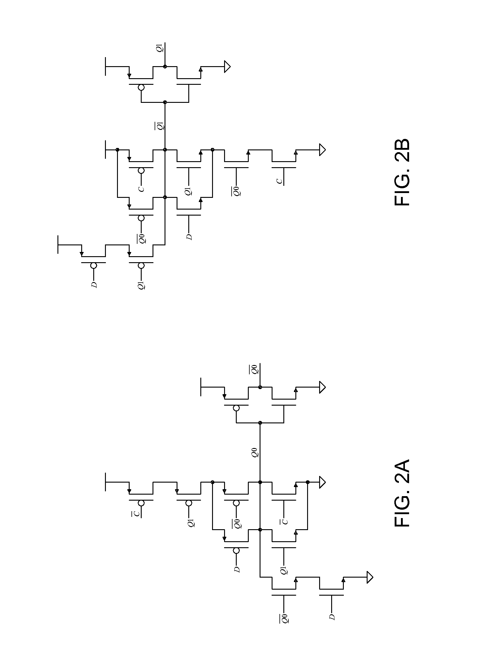
[0032]FIG. 1 is a schematic block diagram of a column-parallel single-slope ADC of the prior art, which has N columns which operate in parallel. In each column there is provided a comparator 120, for example an operational amplifier, which compares an input voltage (Vin1, . . . , VinN) for the respective column with a ramp voltage Vrg by ramp generator 130 that is commonly applied to each of the ADC circuit for each column. This ramp voltage spans the entire input range of the ADC. In the conventional single-slope ADC, the ramp voltage Vrg increases (or decreases) monotonically (which in some cases is a linear change) with time, and can in general be represented by a step function that increases by a predefined increment ΔI after each increment of time Δt. A common digital counter and control 140 is running synchronously with the ramp voltage generator 130. The comparator reports whether the ramp voltage is greater or less than the signal voltage. The latch is edge-triggered by the ...


PUM


Abstract

A latch circuit that uses two interoperating latches. The latch circuit has the beneficial feature that it switches only a single time during a measurement that uses a stair step or ramp function as an input signal in an analog to digital converter. This feature minimizes the amount of power that is consumed in the latch and also minimizes the amount of high frequency noise that is generated by the latch. An application using a plurality of such latch circuits in a parallel decoding ADC for use in an image sensor is given as an example.

Description

CROSS-REFERENCE TO RELATED APPLICATIONS [0001]This application claims priority to and the benefit of co-pending U.S. provisional patent application Ser. No. 61 / 600,410, filed Feb. 17, 2012, which application is incorporated herein by reference in its entirety.STATEMENT REGARDING FEDERALLY FUNDED RESEARCH OR DEVELOPMENT [0002]The invention described herein was made in the performance of work under a NASA contract, and is subject to the provisions of Public Law 96-517 (35 USC 202) in which the Contractor has elected to retain title.THE NAMES OF THE PARTIES TO A JOINT RESEARCH AGREEMENT [0003]NOT APPLICABLEINCORPORATION-BY-REFERENCE OF MATERIAL SUBMITTED ON A COMPACT DISC [0004]NOT APPLICABLEFIELD OF THE INVENTION [0005]The invention relates to electronic circuits in general and particularly to a dual R-S latch.BACKGROUND OF THE INVENTION [0006]Single-slope ADCs are particularly attractive for use in applications such as column-parallel digitization in image sensors because of their re...

Claims


Application Information

Patent Timeline
Patent Type & Authority Applications(United States)
IPC IPC(8): H03K3/037G01R29/00
CPCH03K3/0375H03M1/123G01R29/00H03M1/56H03K3/356104H03K3/012H03M1/002
Inventor HANCOCK, BRUCE R.
Owner CALIFORNIA INST OF TECH
Learn More