Device for Noncontact Determination of Edge Profile at a Thin Disk-Shaped Object

a thin disk-shaped object and edge profile technology, applied in the direction of semiconductor/solid-state device testing/measurement, instruments, television systems, etc., can solve the problems of inability to assess defects in this device, corrupt measurement results, even impossible measurement, etc., to achieve accurate edge measurement, simplify image recording description, and determine the edge profile quickly and reliably

Active Publication Date: 2013-08-22
KOCOS AUTOMATION
View PDF0 Cites 22 Cited by
  • Summary
  • Abstract
  • Description
  • Claims
  • Application Information

AI Technical Summary

Benefits of technology

The technical effect of this patented technology allows for accurate measurements with fewer problems than previous methods due to its ability to accurately capture an outline shape without any misalignment between different lights used during photography. Additionally, there're certain advantages over existing techniques such as scanning electron microscopy (SEM). These benefits include faster processing times and improved accuracy while capturing detailed features like sharp corners from imperfections in the surface being measured.

Problems solved by technology

The patent text describes two devices for inspecting defects on the edge of a wafer. The first device uses three cameras to capture images of the edge region from different angles. The images are then displayed on a monitor for visual evaluation. The second device uses a CCD line camera to capture images of the edge region from a single perspective. The device also includes an illumination system to capture the images. The technical problem addressed in this patent is the need for an objective, qualitative assessment of defects on the wafer edge, rather than just a subjective evaluation.

Method used


Image

  • Device for Noncontact Determination of Edge Profile at a Thin Disk-Shaped Object
  • Device for Noncontact Determination of Edge Profile at a Thin Disk-Shaped Object
  • Device for Noncontact Determination of Edge Profile at a Thin Disk-Shaped Object

Examples


Embodiment Construction

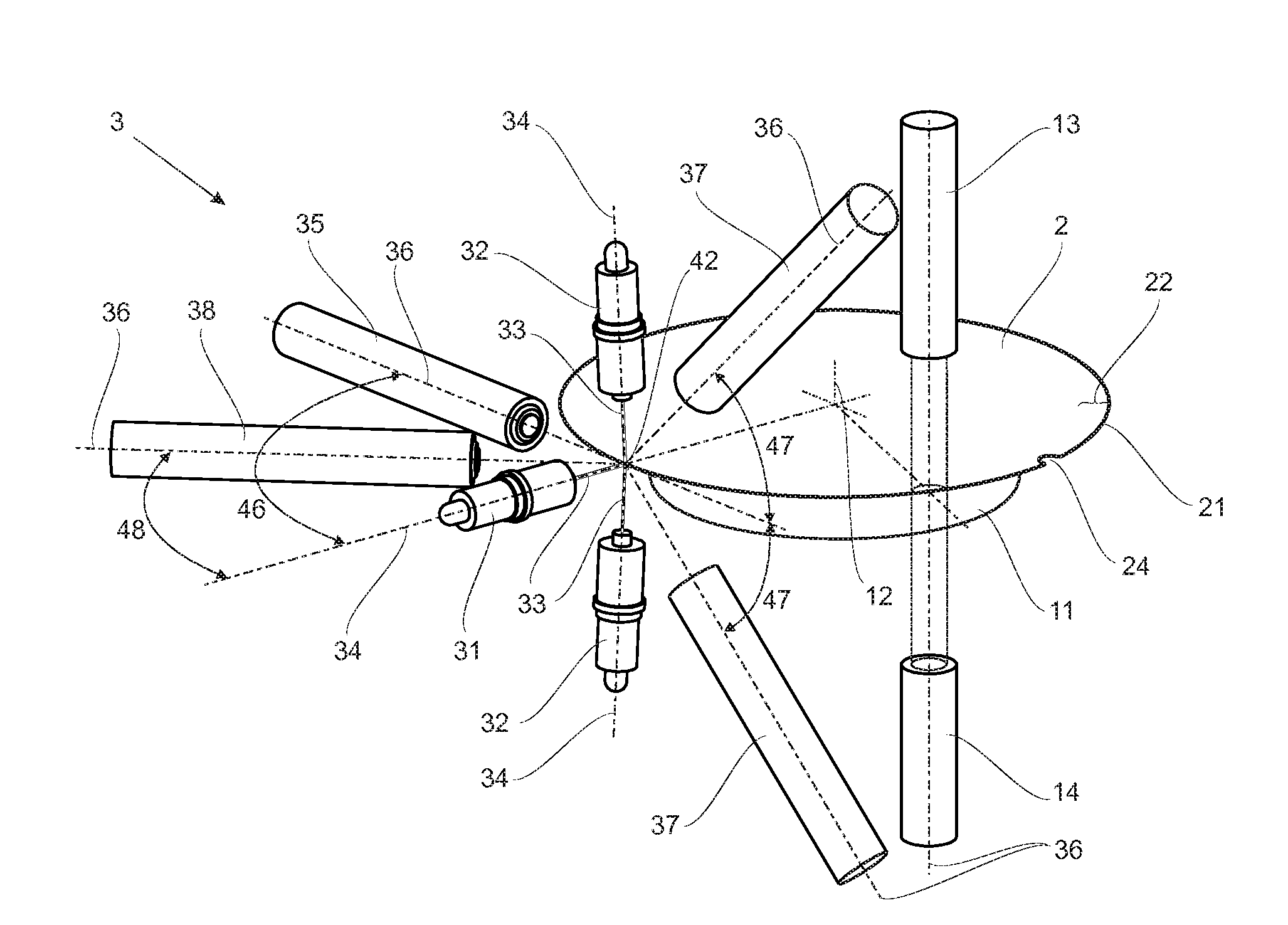
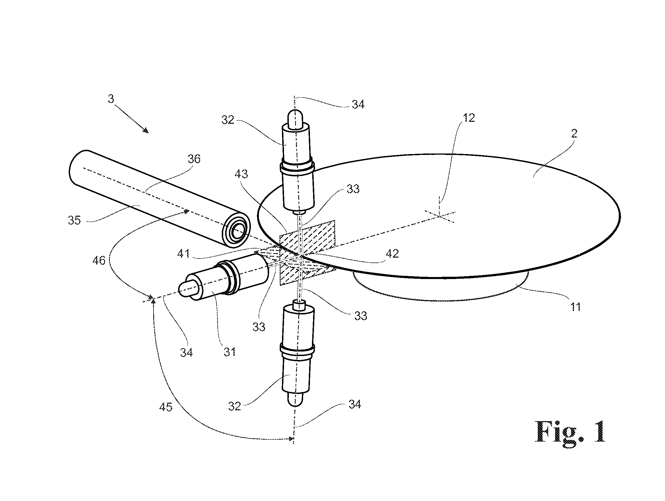
[0022]According to FIG. 1, the device has a measuring arrangement 3 including a base laser radiation source 31, at least two further laser radiation sources 32 and at least one base camera 35. The optical axis 34 of the base laser radiation source 31 and the optical axis 36 of the base camera 35 are arranged substantially orthogonal to one another in a preferably horizontally oriented common base plane 41 and meet at an intersection 42. The further laser radiation sources 32 are arranged with their optical axes 34 symmetric to both sides of the base laser radiation source 31 in a measurement plane 43 at an irradiation angle 45 of the same size but different sign relative to the base laser radiation source 31 and are likewise directed into intersection 42. The laser radiation sources 31 and 32 are preferably line lasers of identical construction and have line-shaped beam profiles whose light bundles 33 collectively form a light sheet 4 inside the measurement plane 43. The light sheet...


PUM


Abstract

A device for noncontact determination of the edge profile at a thin disk-shaped object helps determining the edge profile at semiconductor wafers in which exact image recording is not impaired by specular reflections of the edge profile. A plurality of light sources in the form of laser radiation sources each emitting a line-shaped light bundle are arranged so as to be coplanar in a common plane representing a measurement plane oriented orthogonal to a base plane of the object and are directed from different directions to a common intersection of the laser radiation sources in the edge region of the object. A light sheet is formed in the measurement plane and at least one base camera is directed in the base plane lateral to the measurement plane to capture scattered light proceeding from a light line generated by the light sheet when impinging the object edge region.

Description


Claims


Application Information

Patent Timeline
Owner KOCOS AUTOMATION
Why Eureka
Try Eureka