Strobe device

Inactive Publication Date: 2013-08-22
STANLEY ELECTRIC CO LTD
View PDF1 Cites 4 Cited by
  • Summary
  • Abstract
  • Description
  • Claims
  • Application Information

AI Technical Summary

Benefits of technology

[0017]Thus, since the projecting portion is provided on the electrically-conductive surface of the reflector, when a trigger voltage is applied, it is possible to stably supply the voltage to the electron source. Hereby, even in a case where a length of the reflector is shortened while a length of the tube is maintained so that “the cathode-side end of the electrically-conductive surface” is positioned closer

Problems solved by technology

At this time, if a length of a xenon tube is also shortened as well as the length of the reflector, luminance of strobe light is decreased, thereby impairing functionality as the strobe device.
In this case, there is a possibility that a trigger voltage applied to the electrically-conductive surface of the

Method used


Image

  • Strobe device
  • Strobe device
  • Strobe device

Examples


Embodiment Construction

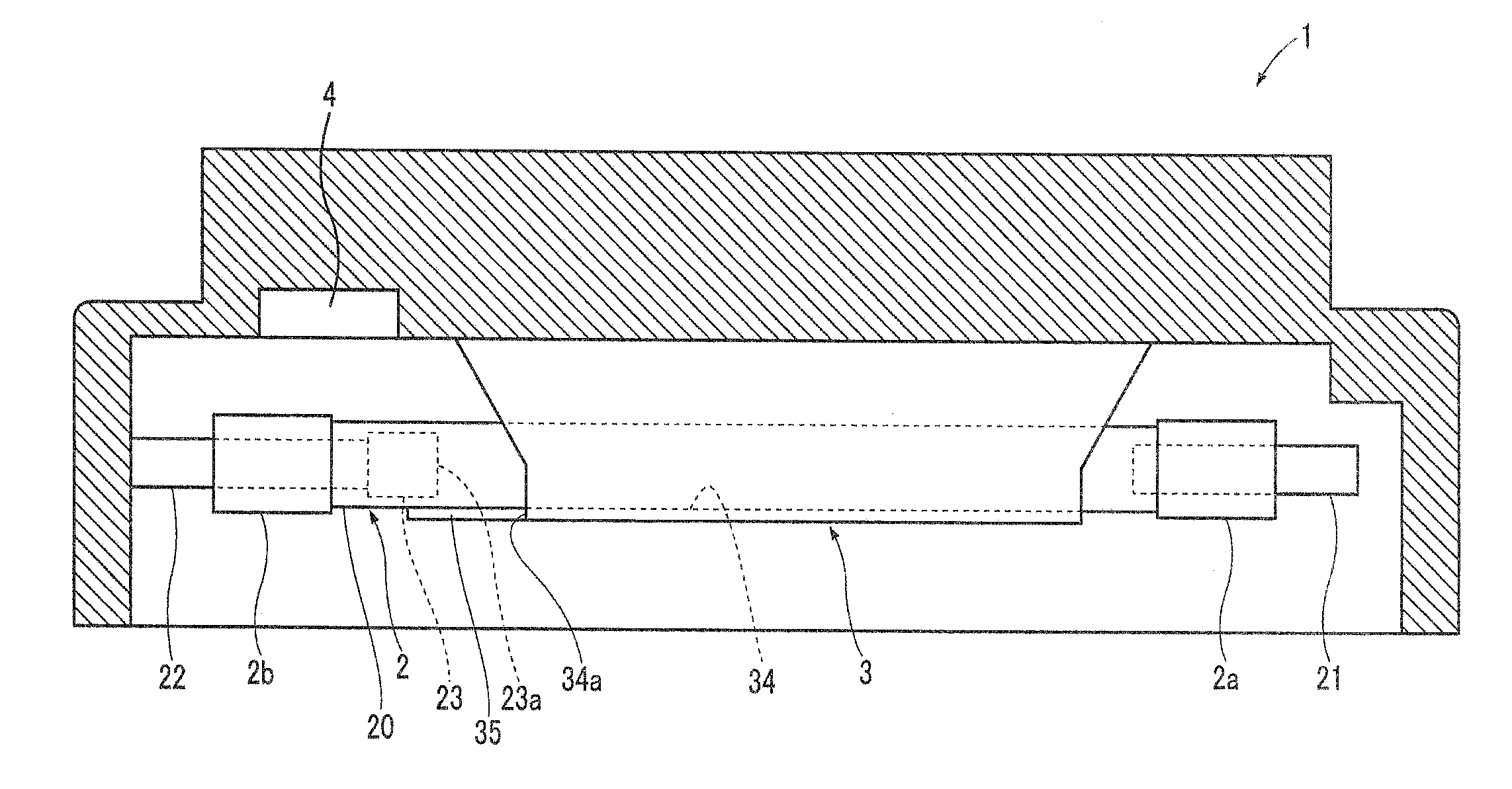
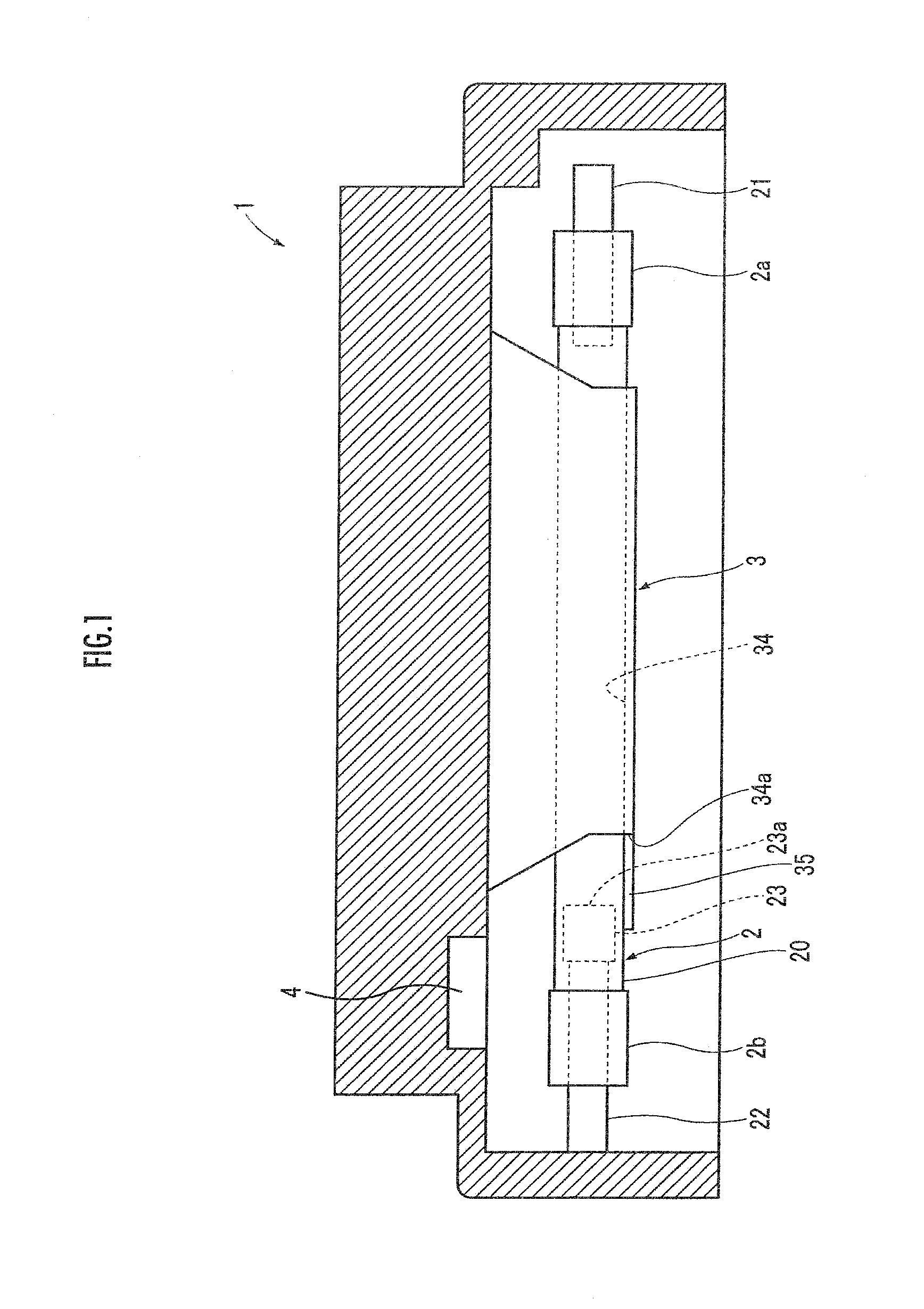
[0023]The following describes a configuration of a strobe device of an embodiment of the present invention. A strobe device 1 of the present embodiment is provided, for example, in a mobile phone equipped with a camera function.

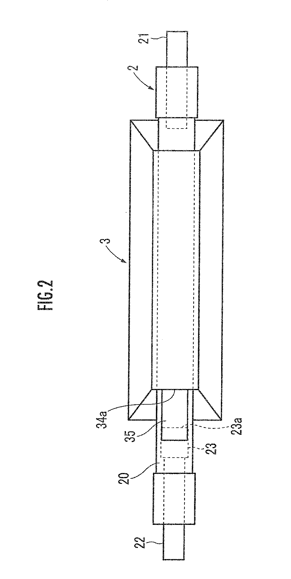
[0024]As illustrated in FIGS. 1 and 2, the strobe device 1 includes a xenon tube 2, a reflector 3, and an auxiliary-light emitting section 4.

[0025]The xenon tube 2 includes a cylindrical glass tube 20 including large-diameter portions 2a and 2b at both ends. Xenon gas is enclosed in the glass tube 20. A transparent electrode (not illustrated) constituting a trigger electrode for applying a trigger voltage for light emission is applied on an outer surface of this glass tube 20. Further, the xenon tube 2 includes an anode 21 and a cathode 22 at both ends thereof.

[0026]Further, the xenon tube 2 includes a sintered body 23 having electric conductivity and electrically connected to the cathode 22, at the cathode-22 side inside the xenon tube 2. The sintered body 2...


PUM


Abstract

A strobe device 1 includes an electrically-conductive reflector 3 into which a xenon tube 2 having xenon gas enclosed therein and having a light-transmitting property is housed. The xenon tube 2 has an anode 21 and a cathode 22 at both ends, and a sintered body 23 electrically connected to the cathode 22 at the cathode-22 side inside the xenon tube 2. A cathode-22-side end 34a of a bottom surface 34 of the reflector 3 is positioned closer to the anode-22 side than the sintered body 23. The bottom surface 34 is provided with an electrically-conductive projecting portion 35 projecting from the cathode-22-side end 34a so as to be closer to the cathode-22 side than the anode-side end 23a of the sintered body 23.

Description

BACKGROUND OF THE INVENTION[0001]1. Field of the Invention[0002]The present invention relates to a strobe device including a discharge tube having rare gas enclosed therein.[0003]2. Description of the Related Art[0004]There has been conventionally known a strobe device in which a xenon tube having xenon gas enclosed therein is housed in a reflector having an opening on a front side (Patent Document 1). In this strobe device, both ends of the xenon tube stick out from side surfaces of the reflector.[0005]Generally, in such a xenon tube, an anode and a cathode are formed at both ends of a glass tube forming an outer frame thereof. Further, the xenon tube is provided with a sintered body electrically connected to the cathode and having electric conductivity at a cathode side inside the xenon tube. This sintered body functions as an electron source having a property to emit electrons which excite xenon gas when a voltage is applied.[0006]Further, generally, such a reflector has a surfac...

Claims


Application Information

Patent Timeline
IPC IPC(8): G03B15/03
CPCG03B2215/0582G03B15/03
Inventor YONEYA, TAKAYUKIMIYAZAWA, ATSUMI
Owner STANLEY ELECTRIC CO LTD
Why Eureka
Try Eureka