

Ligature-resistant lavatory assembly and adjustable faucet and valve
- Summary
- Abstract
- Description
- Claims
- Application Information
AI Technical Summary
Benefits of technology
Problems solved by technology
Method used
Image

Examples
Embodiment Construction
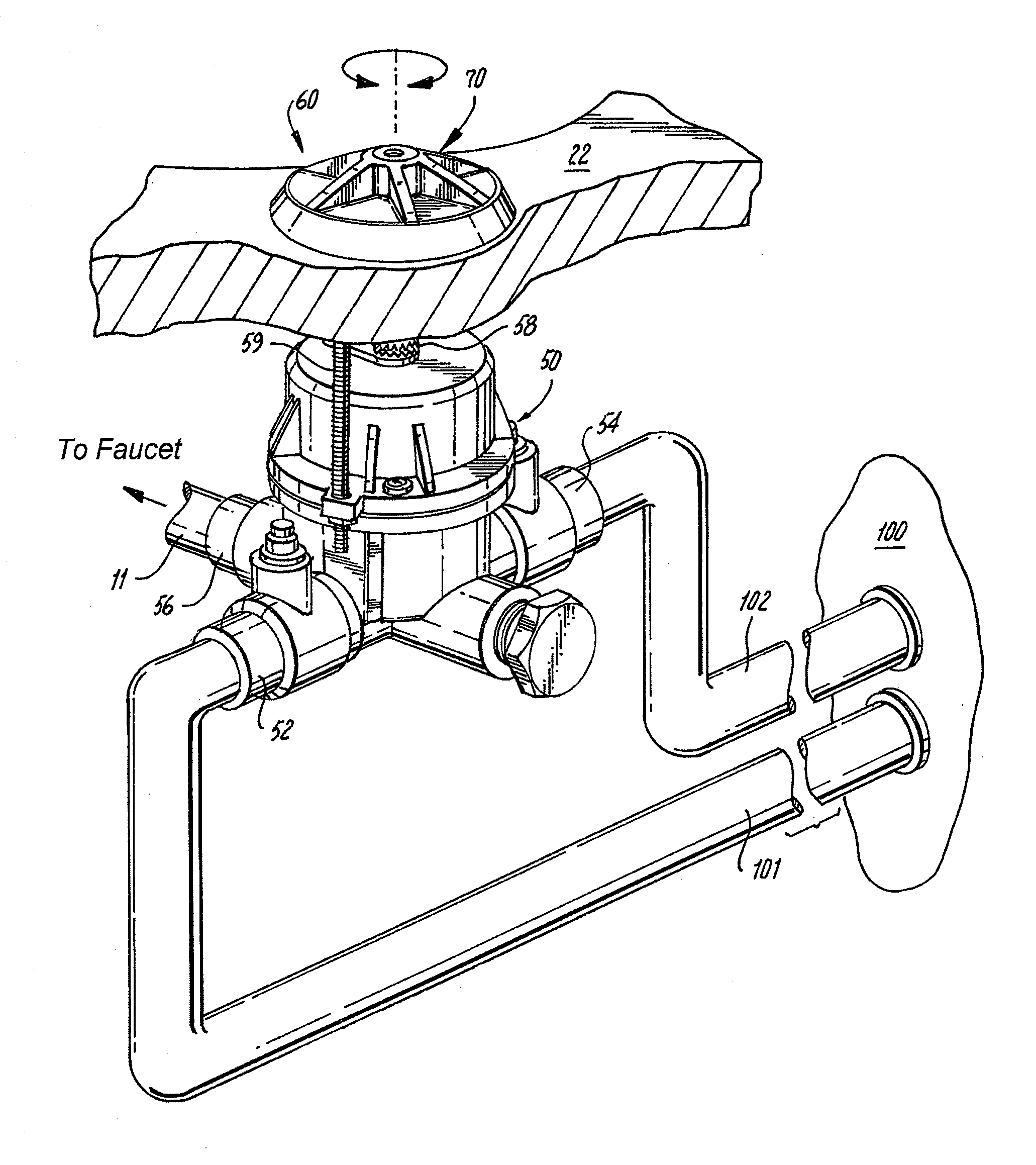
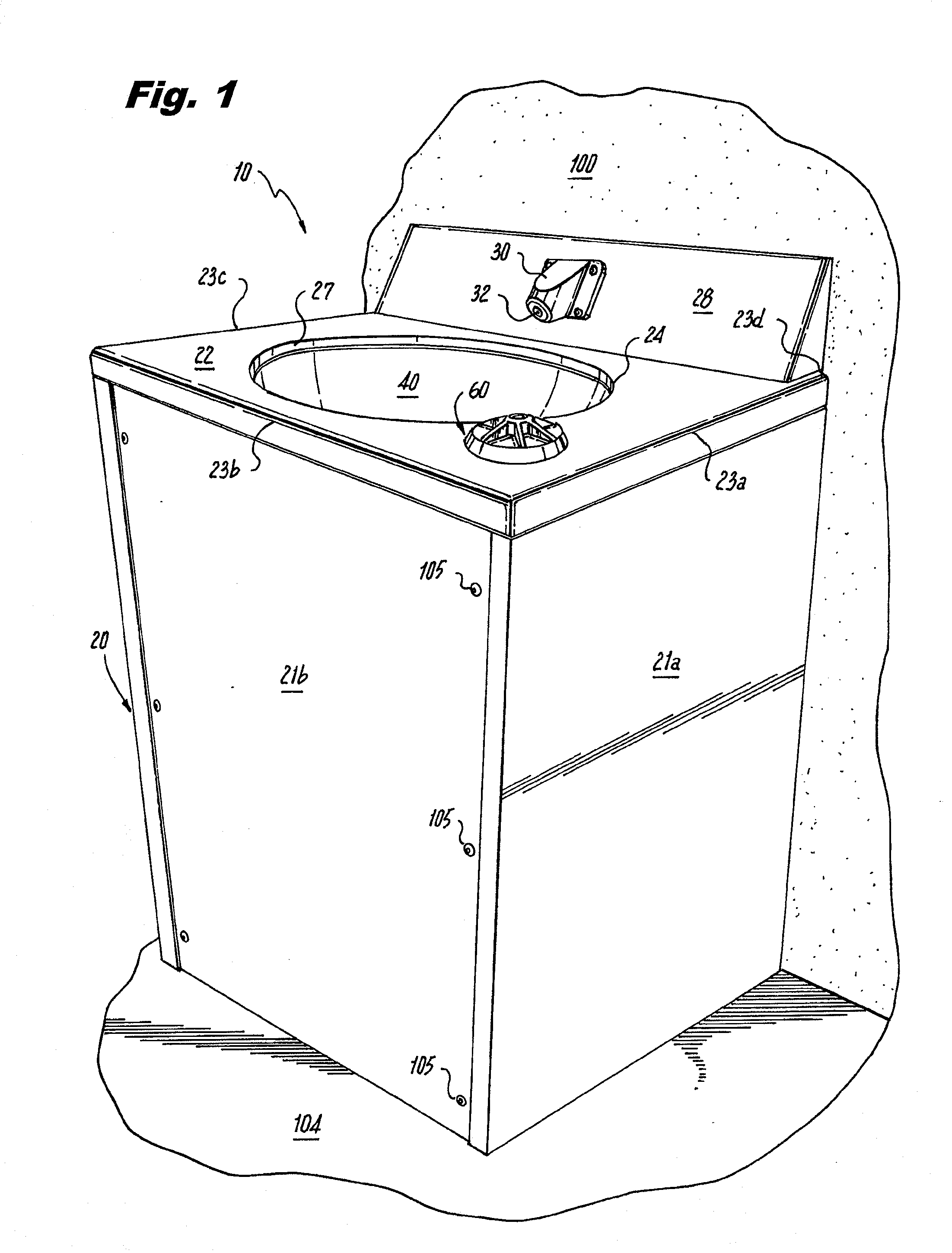
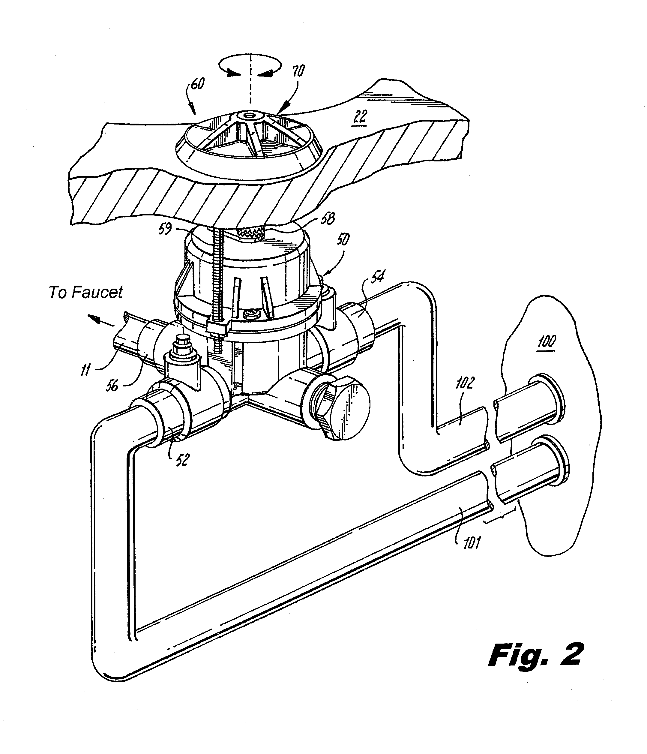
[0040]Turning now in detail to the drawings, and in particular, FIG. 1, therein illustrated is a novel, ligature-resistant lavatory assembly, generally designated by reference numeral 10, incorporating a ligature-resistant faucet and valve assembly, generally designated by reference numeral 60, embodying the present invention.
[0041]As seen in FIG. 1, ligature-resistant lavatory assembly 10 includes a vanity or housing 20 which is mounted against and affixed to a wall 100 and which is particularly suitable for behavioral health facilities, psychiatric facilities, or prisons. As seen best in FIGS. 2 and 4, wall 100 includes an ingoing hot water supply line 101, an ingoing cold water supply line 102, and an outgoing waste or drain line 103. Cabinet or housing 20 can also be secured to floor 104, to prevent a patient / inmate from kicking in or otherwise removing housing 20.
[0042]As seen best in FIG. 1, housing 20 preferably has three vertical sidewalls 21a, 21b, and 21c (not shown) and a...
PUM
 Abstract
Description
Claims
Application Information