Lens for Wide Lateral-Angle Distribution

a wide-angle, lateral-angle technology, applied in the field of light systems, can solve the problems of increased overall cost of led lighting using such lenses, inability to provide the light distribution required for proper illumination of wide target surfaces, and difficulty in manufacturing, so as to facilitate wide-angle distribution, facilitate uniform light distribution, and facilitate uniform light distribution

Active Publication Date: 2013-08-29
IDEAL IND LIGHTING LLC
View PDF3 Cites 13 Cited by
  • Summary
  • Abstract
  • Description
  • Claims
  • Application Information

AI Technical Summary

Benefits of technology

[0010]In certain embodiments, the inner front and back surface portions are substantially orthogonal to the inner lateral surface portion. In some of such embodiments, the cavity opening is substantially rectangular. The term “substantially rectangular,” as used herein with respect to the cavity opening, means (1) that the cavity opening has four sides and (2) that at least about one-third of the cross-dimension of each side of the cavity opening is straight or that at least about one-third of the cross-dimension of the longer sides (if there is a pair of longer sides) is substantially straight. (It should be recognized that the “square” is a subset of “rectangular.”) It should be noted that while rounded corners of the cavity opening and of the surrounding inner wall do not impact the distribution of light in a significant way, such rounding provides advantages during manufacturing of the inventive lens. In particular, the minimizing of sharpness at corners facilitates accurate molding of the inventive lens.
[0017]The intermediate lateral surface portions may have substantially-identical lateral curvatures which differ from the configurations of the front and back curvatures. Another aspect of the rounded corners of the cavity opening and a base edge of the intermediate surface is that such rounding provides smooth transition from the lateral curvatures to the front and back curvatures of the intermediate surface.
[0018]In certain embodiments, the outer output surface includes a main output surface portion transverse the axis. In some of such embodiments, the main-output surface portion defines a pair of substantially convex lateral sectors with a front-to-back concavity therebetween for refracting lateral light received from the inner surface laterally away from the axis to facilitate wide lateral-angle distribution. The main output surface portion may be configured for refracting forward and rearward light received from the inner front and back surface portions away from the axis to facilitate uniform distribution of light. To further facilitate uniform distribution of light, the main output surface may be configured for refracting light received from the front and back reflecting surface portions toward the axis.
[0025]When the inventive lens is installed for illumination of a surface such as a billboard of a transportation sign, the configuration of the inner end surface portion in combination with the configuration of the main output surface facilitates directing light for an extended lateral distance along the longer dimension of the illuminated surface. In such applications, the combination of the reflecting surface portions and the configuration of the main output surface narrows the front-to-back light spread to provide desirable maximum illumination along substantially the entirety of the shorter dimension of the illuminated surface. This creates a long and narrow illumination pattern that meets the needs for sign or billboard illumination, but may also be used for illuminating facades of buildings and other surfaces.

Problems solved by technology

Some of such lenses are difficult and expensive to manufacture, which increases overall cost for LED lighting using such lenses.
Yet such lenses fall short in providing light distribution required for proper illumination of wide target surfaces.

Method used


Image

  • Lens for Wide Lateral-Angle Distribution
  • Lens for Wide Lateral-Angle Distribution
  • Lens for Wide Lateral-Angle Distribution

Examples


Embodiment Construction

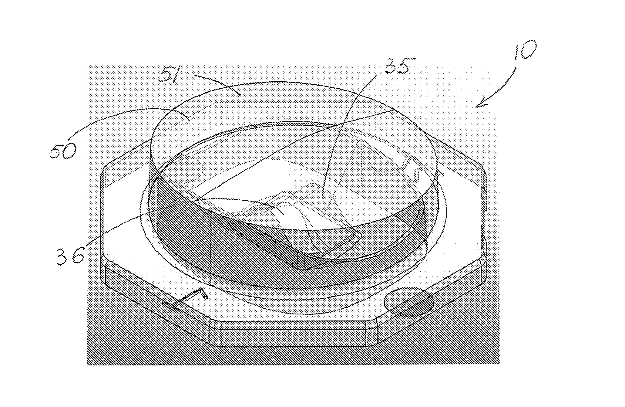
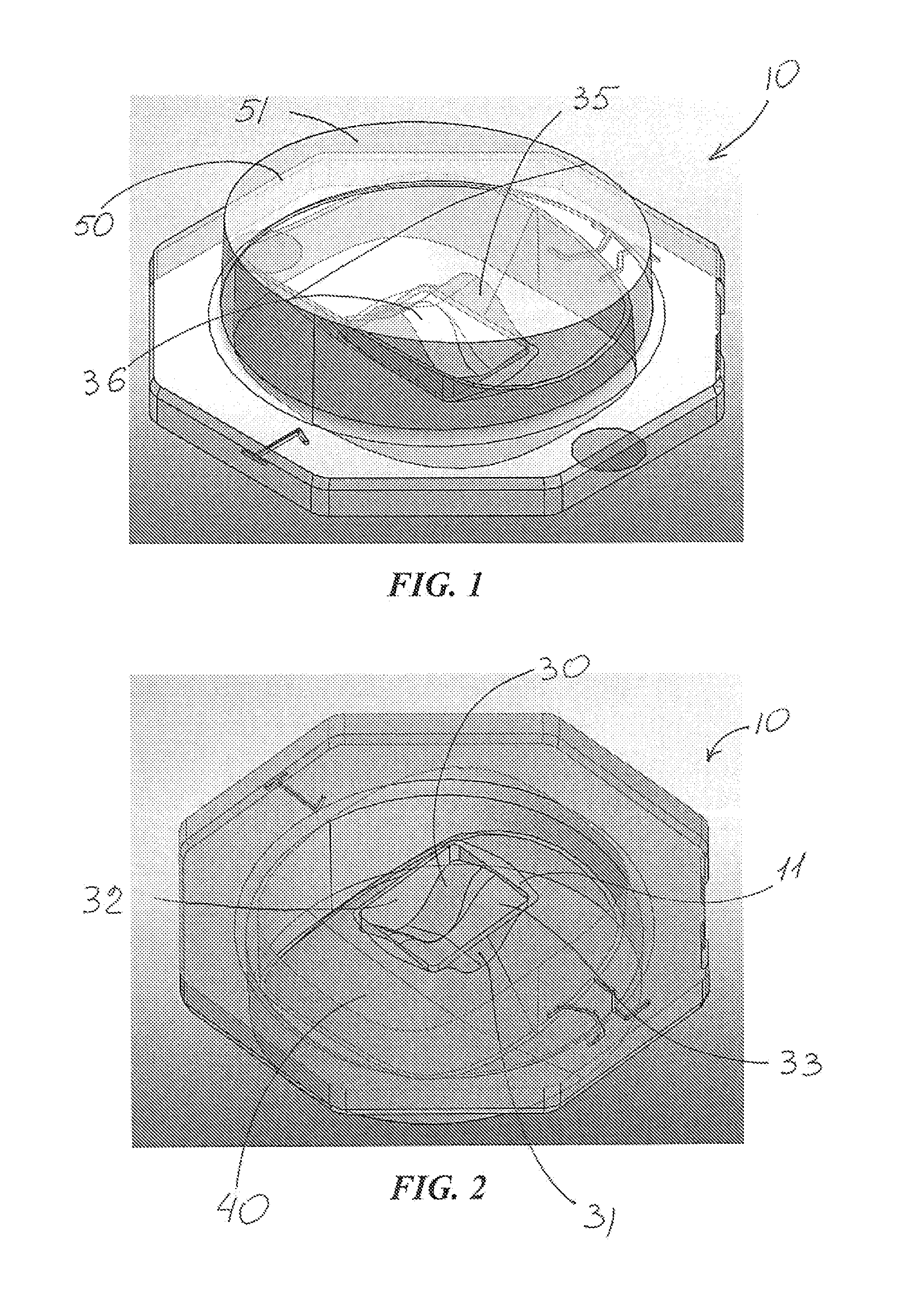
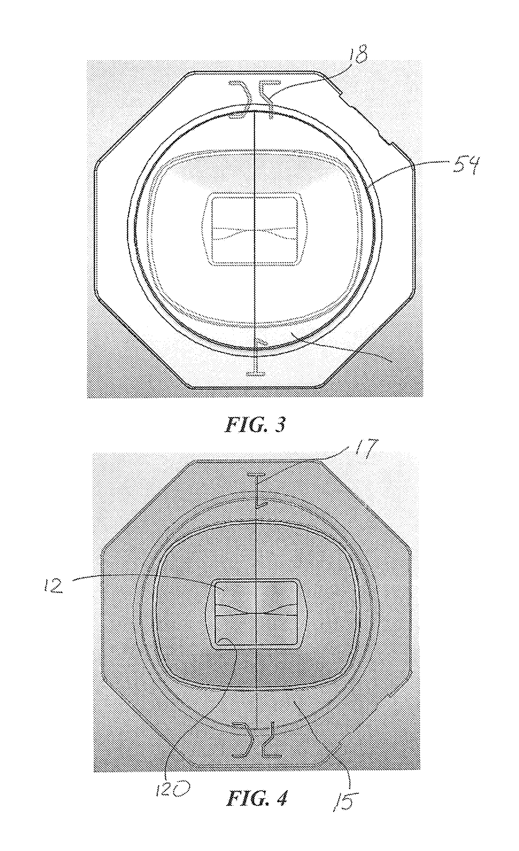
[0065]FIGS. 1-26 show aspects of an exemplary embodiment of a lens 10 in accordance with this invention. Lens 10 is configured for directing light from a light source 20 on a board and defining an axis 6. The light source may be an LED emitter which includes a single LED (or a closely-spaced group of LEDs) mounted either directly on the board or in the form of an LED package with the LED(s) on a submount on the board. A primary lens may be disposed over the LED(s). In such embodiments, lens 10 is a secondary lens placed over the primary lens as seen in FIGS. 17 and 19.

[0066]FIGS. 1-7, 15 and 17 illustrate lens 10 which includes a board-adjacent base 11 spaced from and around axis 6, an inner surface 30, an intermediate surface 40 and an outer output surface 50. As seen in FIGS. 17 and 19, outer output surface 50 is configured for refracting light received from inner surface 30 and intermediate surface 40. As best seen in FIGS. 2, 9, 15 and 16, base 11 forms an opening 12 into a ligh...


PUM


Abstract

A lens for wide lateral-angle distribution of light from an LED light source on a board and defining an axis. The lens includes a board-adjacent base spaced from and around the axis, an inner light-receiving surface, an intermediate surface and an outer output surface configured for refracting light received from the inner and intermediate surfaces. The base forms an opening into a light-receiving cavity defined by the inner surface which includes (a) substantially planar front and back surface portions each extending from the opening and (b) an end surface portion spanning the cavity between the front and back surfaces and comprising front and back segments extending inwardly from the front and back surface portions, respectively, and each angled with respect to the other. The intermediate surface is positioned and configured for reflecting light received from the inner surface toward the outer output surface.

Description

RELATED APPLICATION[0001]This application is a continuation-in-part of currently-pending patent application Ser. No. 13 / 466,076, filed May 7, 2012, which is a continuation-in-part of currently-pending patent application Ser. No. 13 / 408,882, filed Feb. 29, 2012. The entire contents of both parent applications are incorporated herein by reference.FIELD OF THE INVENTION[0002]The invention relates generally to the field of lighting systems and, more particularly, to apparatus for utilizing LED light sources for illuminating areas with a predefined pattern of light intensity.BACKGROUND OF THE INVENTION[0003]There is a need for lighting apparatus which is low-cost and energy efficient. LEDs (light-emitting diodes) provide light sources which are energy efficient, and advances in LED technology are providing even greater efficiencies over time. Some typical applications for lighting systems are roadway and parking lot lighting in which there are performance requirements such as the require...

Claims


Application Information

Patent Timeline
Patent Type & Authority Applications(United States)
IPC IPC(8): F21V13/04F21V5/00
CPCF21V5/04F21W2131/103F21Y2101/02G02B19/0061F21V5/007G02B19/0066F21V13/04F21Y2115/10
Inventor CASTILLO, MARIO ALBERTO
Owner IDEAL IND LIGHTING LLC
Why Eureka
Try Eureka