Image forming apparatus
- Summary
- Abstract
- Description
- Claims
- Application Information
AI Technical Summary
Benefits of technology
Problems solved by technology
Method used
Image

Examples
embodiment 1
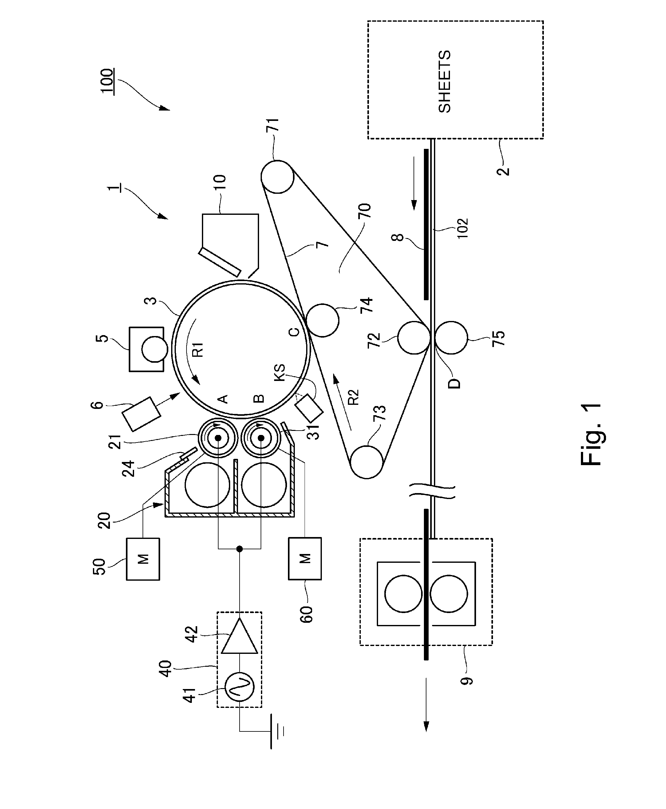
[0116]Referring to FIG. 1, a combination of the charging device 5 and exposing device 6, which is an example of means for forming an electrostatic image, forms an electrostatic image on the peripheral surface of the photosensitive drum 3 which is an example of photosensitive member. An electrostatic image is made up of an actual image portion, that is, the portion of the electrostatic image, to which toner is to adhere as the electrostatic image is developed, and a background portion, that is, the portion of the electrostatic image, to which toner is not to adhere when the electrostatic image is developed.
[0117]The upstream development roller 21, which is an example of the first development roller, bears developer which is a mixture of toner, and carrier which is lower in volume resistivity than the toner. As development bias, that is, a combination of DC voltage and AC voltage, is applied to the upstream development roller 21, the roller 21 develops the electrostatic image on the p...
embodiment 2
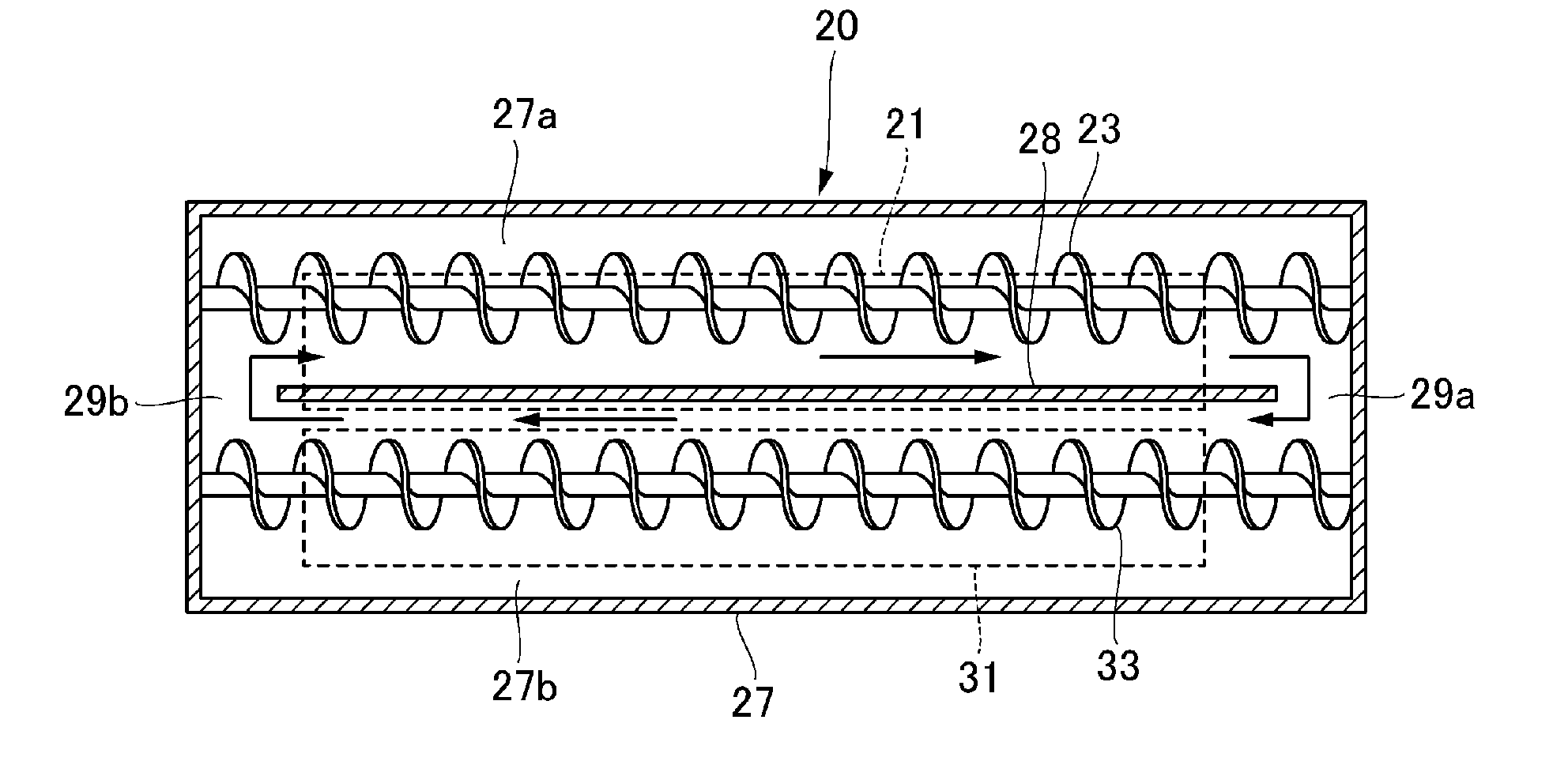
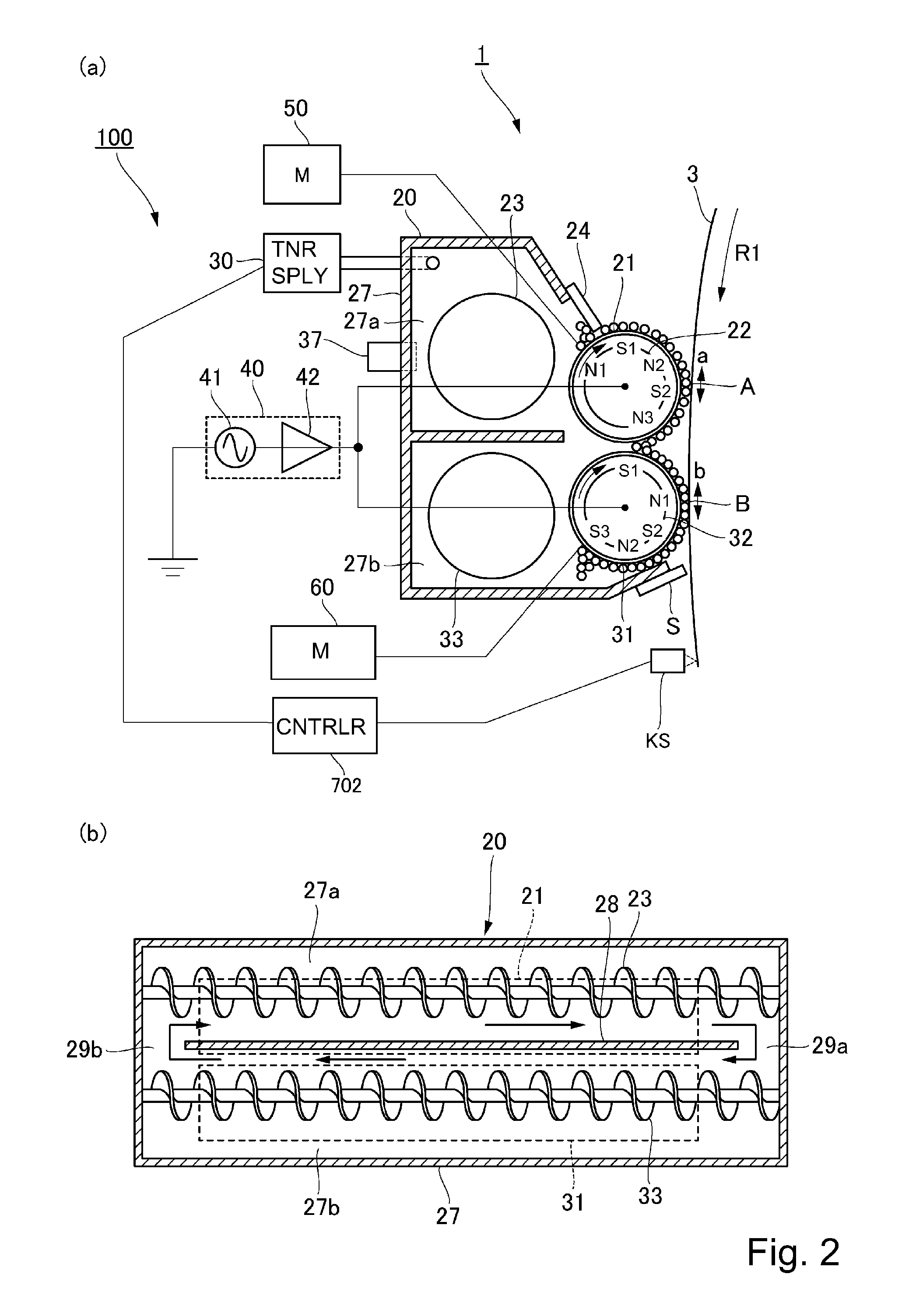
[0129]The developing apparatus in the second embodiment of the present invention also employs two development rollers as shown in FIG. 2. It is based on the developing device in the first embodiment, being slightly different from the one in the first embodiment in that its upstream and downstream are both variable in peripheral velocity. This developing device is operated to find a range in which the developing device tolerable performance in terms of both the development performance and the minimization of toner adhesion to the background. In order to keep the developing device satisfactory for a long time in terms of the minimization (prevention) of the adherence of toner to the background of an electrostatic image, and also, the development performance, an experiment was carried out in which the downstream roller, to which the developer which tends to cause toner to adhere to the background portion of an electrostatic image is transferred from the upstream development roller, was...
embodiment 3
[0142]FIG. 11 is a schematic sectional view of the developing device in the third embodiment of the present invention. It shows the general structure of the device. FIG. 12 is a flowchart of the control sequence for the device shown in FIG. 11. FIG. 13 is a drawing of the test electrostatic image used for controlling the developing device in the third embodiment. FIG. 14 is a schematic sectional view of the developing device in the third embodiment, and a part of the peripheral surface of the photosensitive drum, which is for describing the points at which the test electrostatic image is to be detected. FIG. 15 is a graph which shows the relationship between the peripheral velocity ratio of the downstream development roller relative to the photosensitive drum, and the difference between the detected potential level of the upstream and downstream unexposed portions of an electrostatic image, relative to the exposed portion of the electrostatic image, in terms of the moving direction ...
PUM
 Abstract
Description
Claims
Application Information
 - Generate Ideas
- Intellectual Property
- Life Sciences
- Materials
- Tech Scout
- Unparalleled Data Quality
- Higher Quality Content
- 60% Fewer Hallucinations
Browse by: Latest US Patents, China's latest patents, Technical Efficacy Thesaurus, Application Domain, Technology Topic, Popular Technical Reports.
© 2025 PatSnap. All rights reserved.Legal|Privacy policy|Modern Slavery Act Transparency Statement|Sitemap|About US| Contact US: help@patsnap.com