

Power supply apparatus, method of controlling the apparatus, and electronic device using the apparatus
- Summary
- Abstract
- Description
- Claims
- Application Information
AI Technical Summary
Benefits of technology
Problems solved by technology
Method used
Image

Examples
exemplary embodiment 1
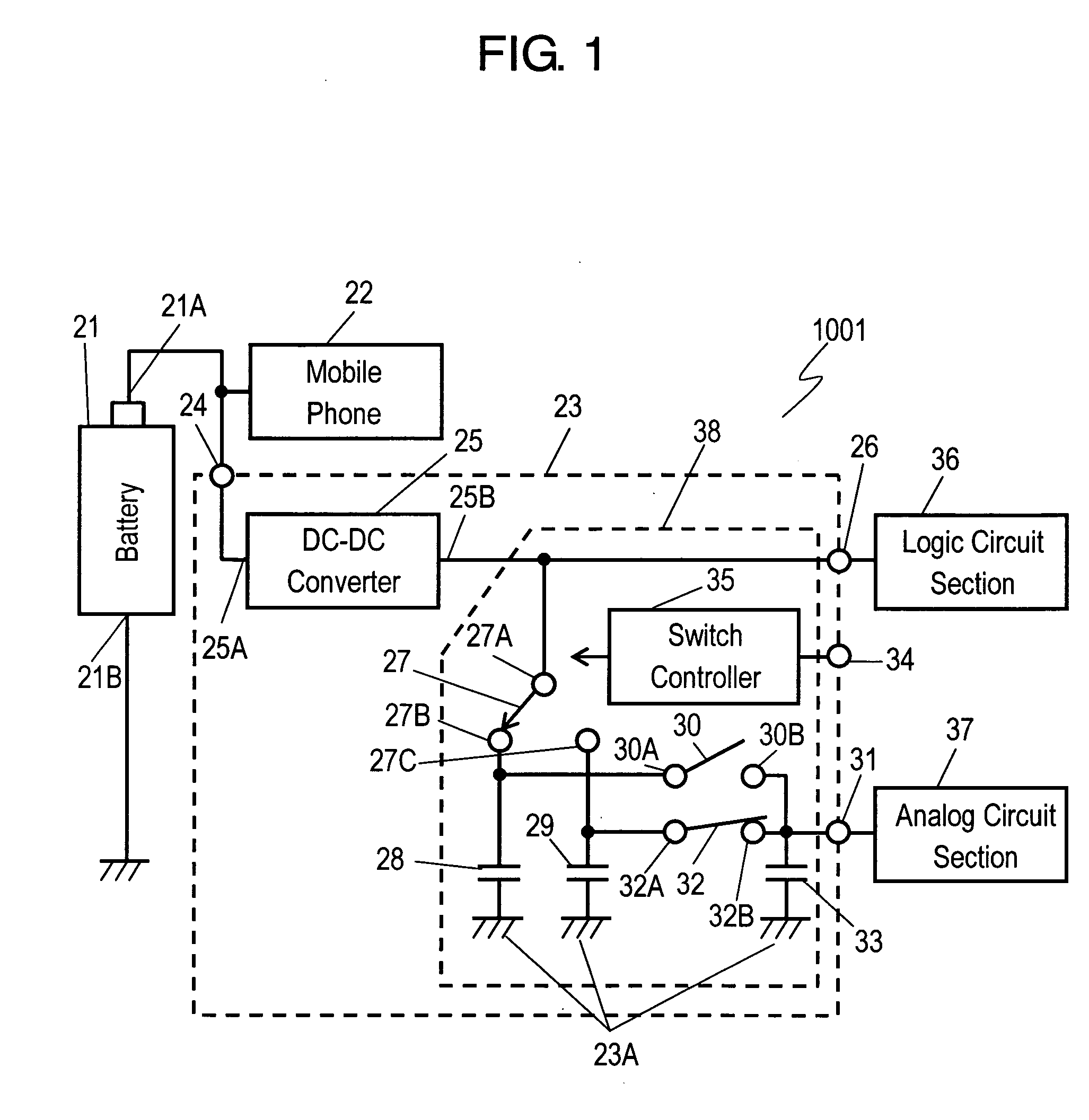
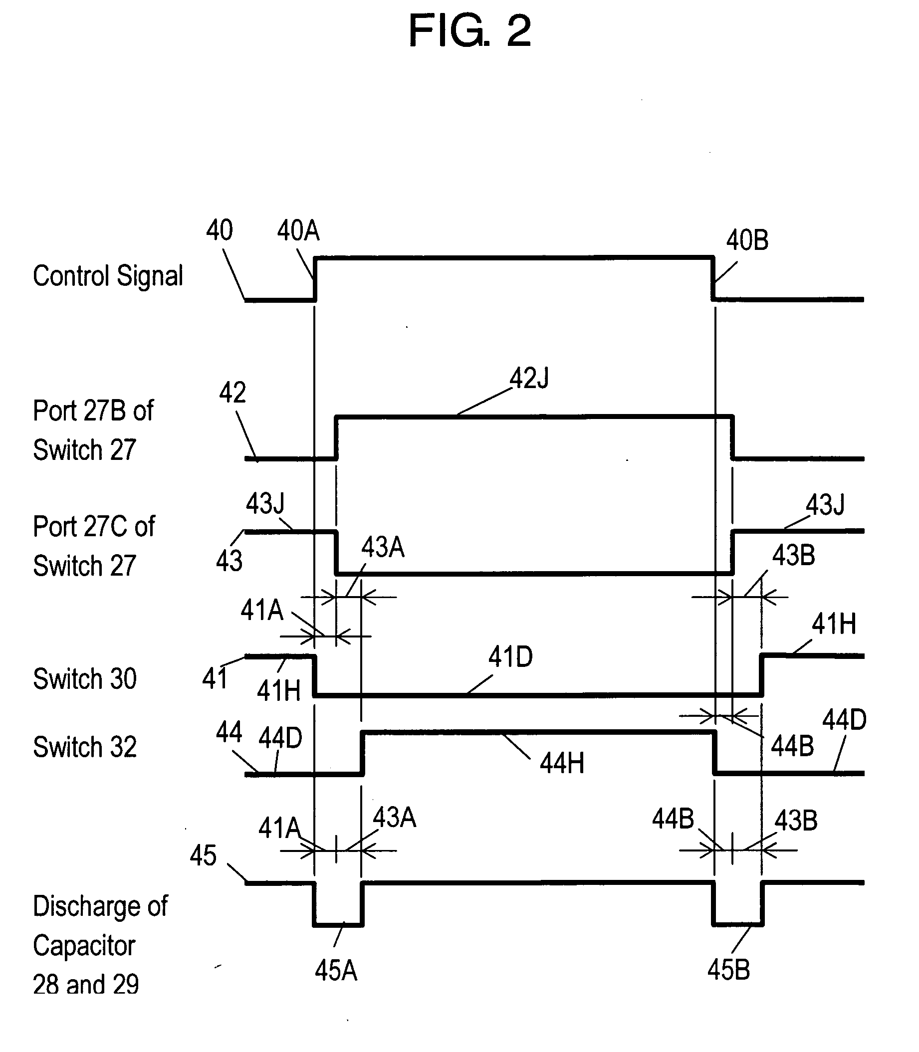
[0021]FIG. 1 is a circuit block diagram of electronic device 1001 including power supply apparatus 23 according to Exemplary Embodiment 1 of the present invention. Battery 21, a direct-current (DC) power supply, has an internal resistor, and outputs a voltage of 3.6V. Positive electrode 21B of battery 21 is connected to ground 1001A, and negative electrode 21A of the battery is connected to mobile phone 22 and input terminal 24 of power supply apparatus 23.
[0022] Electronic device 1001 includes battery 21, mobile phone 22, power supply apparatus 23, logic circuit section 36, and analog circuit section 37. Power supply apparatus 23 includes output terminals 26 and 31 that are connected to logic circuit section 36 and analog circuit section 37, respectively to supply power sources.
[0023] Power supply apparatus 23 includes input terminal 24 and DC-DC converter 25. Input terminal 24 is connected to input port 25A of DC-DC converter 25. Logic circuit section 36 and analog circuit secti...
exemplary embodiment 2
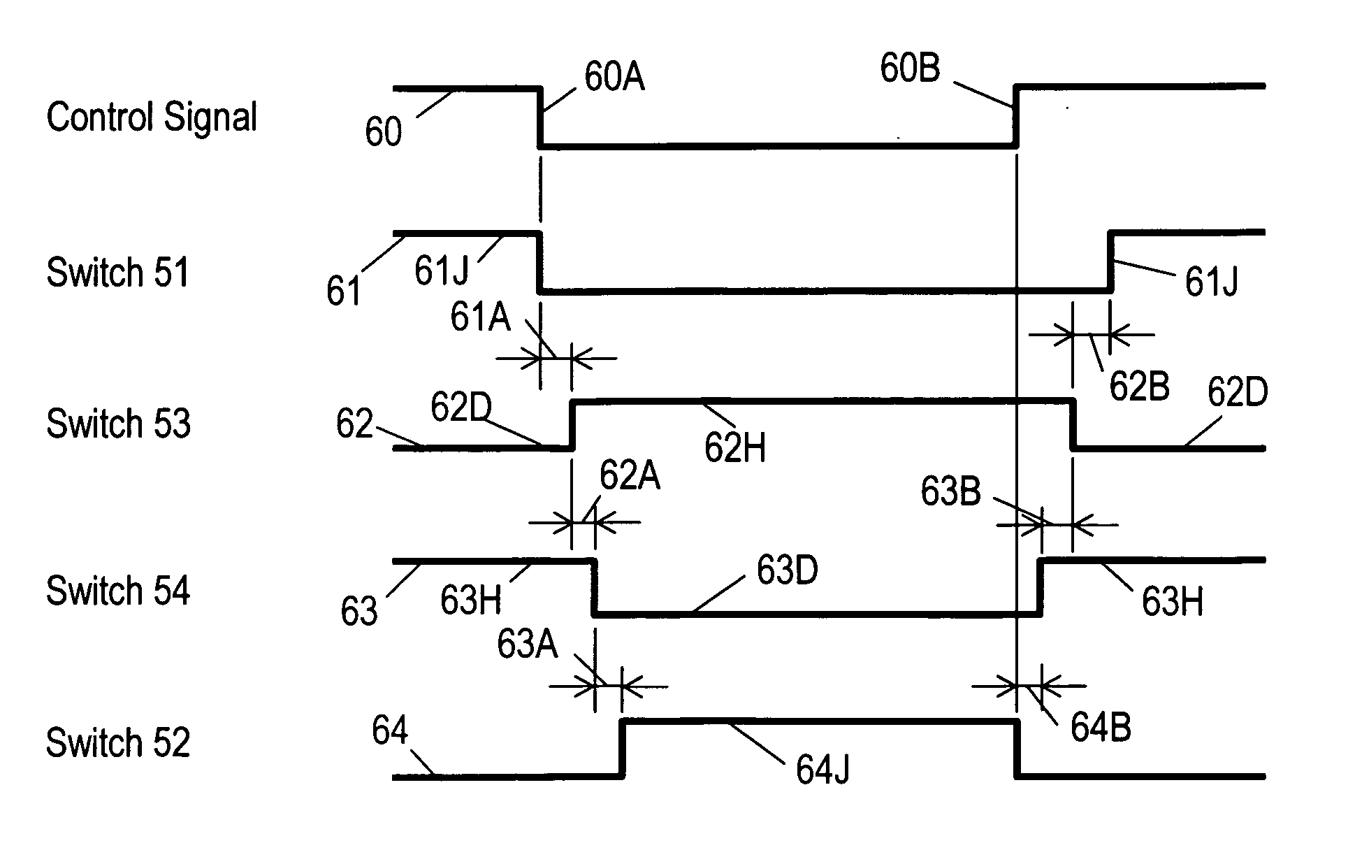
[0043]FIG. 3 is a block diagram of power supply apparatus 50 according to Exemplary Embodiment 2. Power supply apparatus 50 includes switches 51 to 54 instead of branching switch 27 and switches 30 and 32 of power supply apparatus 23 shown in FIG. 1 according to Embodiment 1. In FIG. 3, the same components as those shown in FIG. 1 are denoted by the same reference numerals, and their description will not be omitted.
[0044] Input terminal 24 of power supply apparatus 50 is connected to input port 25A of DC-DC converter 25. Output port 25B of DC-DC converter 25 is connected directly to output terminal 26 and is connected to ports 51A and 52A of switches 51 and 52, respectively. Port 51B of switch 51 is connected to port 53A of switch 53. Port 52B of switch 52 is connected to port 54A of switch 54. Ports 53B and 54B of switches 53 and 54 are connected to output terminal 31, respectively.
[0045] Port 51B of switch 51 is connected to port 53A of switch 53 at node 155. Capacitor 55 is con...
exemplary embodiment 3
[0055]FIG. 5 is a block diagram of power supply apparatus 150 according to Exemplary Embodiment 3. Power supply apparatus 150 includes switches 152(1) to 152(N) and 153(1) to 153(N) instead of branching switch 27 and switches 30 and 32 of power supply apparatus 23 shown in FIG. 1 according to Embodiment 1. Power supply apparatus 150 further includes capacitors 154(1) to 154(N) instead of capacitors 28 and 29. Input terminal 24 of power supply apparatus 150 is connected to input port 25A of DC-DC converter 25. Output port 25B of DC-DC converter 25 is directly connected to output terminal 26. The number “N” of charge / discharge circuits 151(1) to 151(N) are connected in parallel with each other between output port 25B of DC-DC converter 25 and output terminal 31.
[0056] All charge / discharge circuits 151(1) to 151(N) have structures identical to each other. The k-th charge / discharge circuit 151(k) (1≦k≦N) out of the number “N” of charge / discharge circuits 151 includes switch 152(k), swi...
PUM
 Abstract
Description
Claims
Application Information