
Recording systems and additional output stackers used therewith

Active Publication Date: 2013-04-04
BROTHER KOGYO KK
View PDF2 Cites 4 Cited by
  • Summary
  • Abstract
  • Description
  • Claims
  • Application Information

AI Technical Summary

Benefits of technology

The patent text describes a recording system with an additional output stacker that can detect when a recording medium is jammed in the stacker and quickly switch to a different destination to prevent the jam from spreading throughout the system. The system's controller can directly control the switch, reducing processing time and ensuring more efficient operation. The technical effect is better prevention of recording medium jams in the additional output stacker.

Problems solved by technology

When the time from when the recording medium jam occurs in the additional output stacker until the transport destination of the recording medium is switched to the apparatus-side output tray is prolonged, however, the recording medium jam in the additional output stacker spreads from the additional output stacker throughout the recording system.

Method used


Image

  • Recording systems and additional output stackers used therewith
  • Recording systems and additional output stackers used therewith
  • Recording systems and additional output stackers used therewith

Examples


Embodiment Construction

[0018]Embodiments of the invention now are described in detail with reference to the accompanying drawings, wherein like reference numerals are used for like corresponding parts in the various drawings.

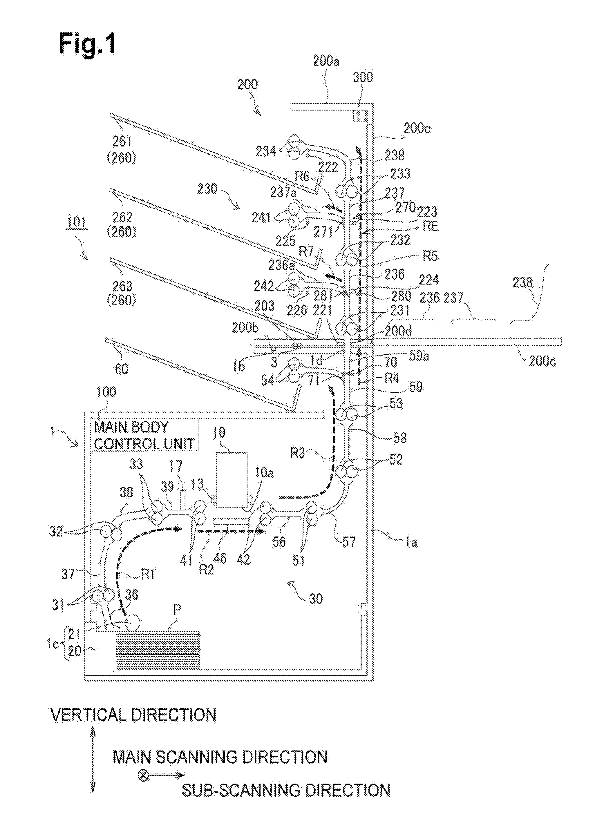
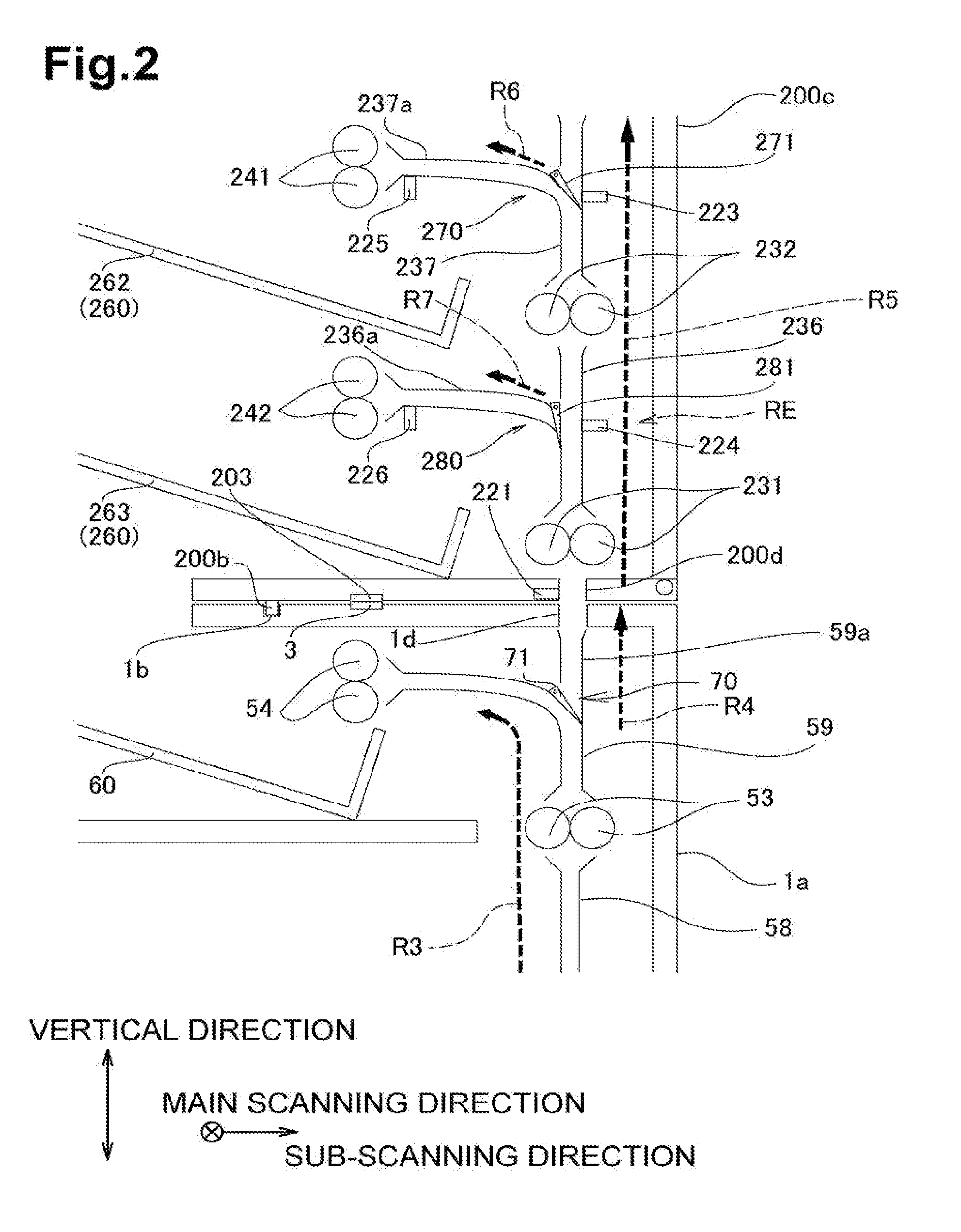
[0019]First, the structure of printer 101 (e.g., a recording system) is described with reference to FIGS. 1 and 2. As depicted in FIG. 1, printer 101 may comprise a main body 1 (e.g., an image recording apparatus) that may be configured to record (e.g., to form) an image on paper P, and an additional paper output unit 200 (e.g., an additional output stacker) that may be attached removably to main body 1.

1. Mechanical Structure of Main Body

[0020]Main body 1 may comprise a cabinet 1a that may be formed in a rectangular parallelepiped shape. A paper output opening 1d may be formed in the top plate of cabinet 1a, and a main body paper output tray 60 (e.g., an apparatus-side output tray), which may be configured to receive paper P, may be provided on the top plate of cabinet 1a, wherein pa...


PUM


Abstract

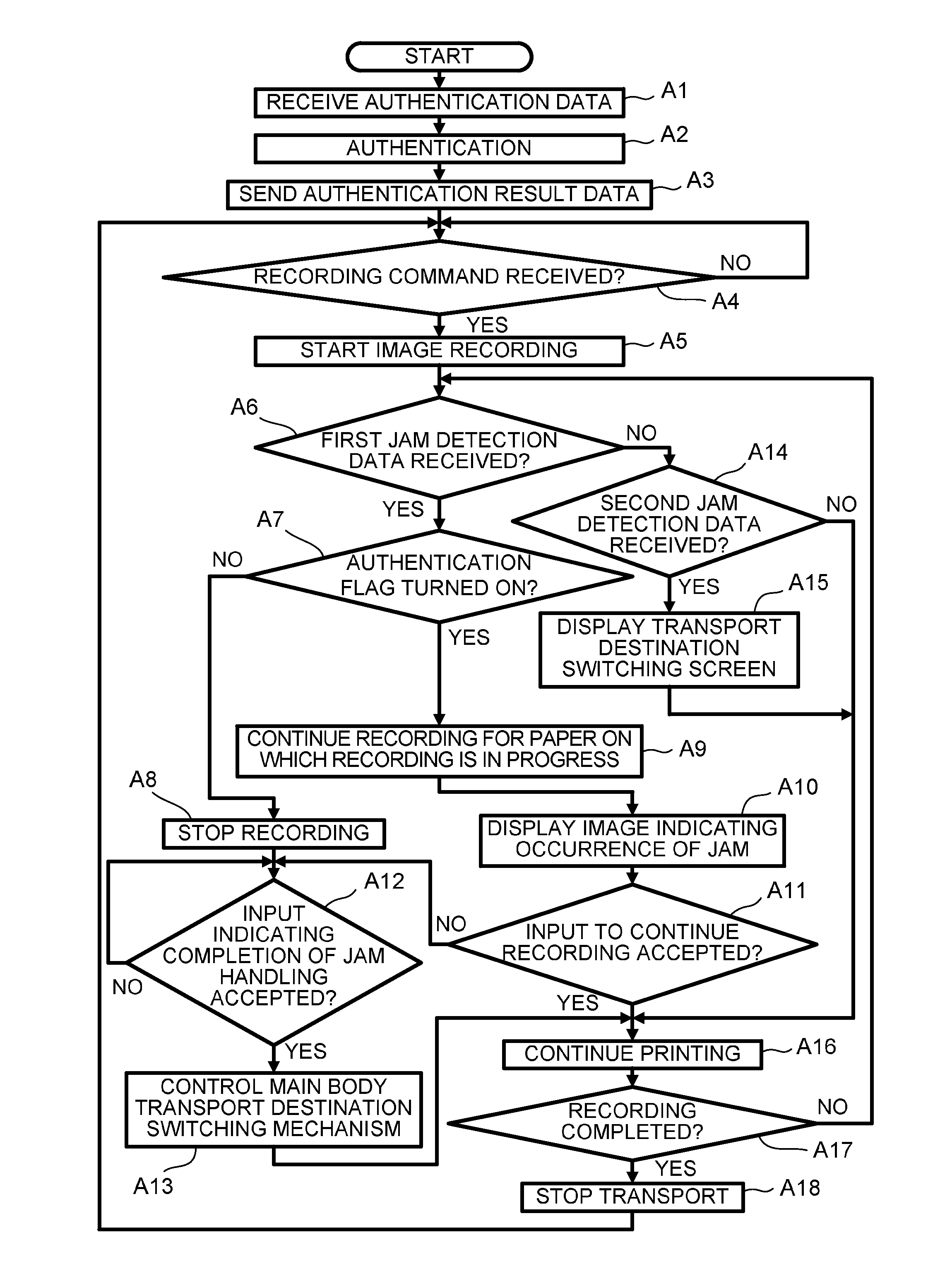
An image recording apparatus includes an apparatus-side transport destination switching unit that may switch selectively the transport destination of paper on which an image has been recorded between an apparatus-side output tray and an additional output stacker. The additional output stacker includes an additional output tray that may be configured to receive paper; a stacker-side transport unit that is configured to transport paper, which has been transported from the image recording apparatus, to the additional output tray; and a stacker-side controller that controls the transport destination switching unit of the image recording apparatus. When a paper jam is detected on the stacker-side transport unit, the additional unit controller controls the apparatus-side transport destination switching unit, so that the transport destination of the paper may be switched from the additional output tray to the apparatus-side output tray.

Description

CROSS REFERENCE TO RELATED APPLICATION[0001]This application claims priority from Japanese Patent Application No. 2011-216604, filed on Sep. 30, 2011, which is incorporated herein by reference.BACKGROUND OF THE INVENTION[0002]1. Field of the Invention[0003]The invention relates to recording systems and paper output stackers used with such recording systems.[0004]2. Description of Related Art[0005]A known recording unit has a plurality of paper output trays. Such recording units are structured, so that, even when an error (i.e., a tray full error) occurs in a paper output tray during use, the printing unit continues printing by outputting paper to another paper output tray.SUMMARY OF THE INVENTION[0006]Some recording systems may be structured, so that an output stacker may be attached optionally to an image recording apparatus in addition to an apparatus-side output tray. With such recording systems, each image recording apparatus and additional output stacker usually has a controlle...

Claims


Application Information

Patent Timeline
IPC IPC(8): B41J29/38
CPCB41J29/38B41J13/0036B41J11/006
Inventor SANO, TOSHIYUKI
Owner BROTHER KOGYO KK
Learn More