Pump or motor for liquid or gaseous media

a technology of gaseous media and push motor, which is applied in the direction of machines/engines, liquid fuel engines, rotary/oscillating piston pump components, etc. it can solve the problems of major power limitation, excessive effort and expense, and the corresponding high demands of rotary bearings and axial bearings, and achieves the effect of producing without major manufacturing expense the working pressure of media

a technology of gaseous media and push motor, which is applied in the direction of machines/engines, liquid fuel engines, rotary/oscillating piston pump components, etc. it can solve the problems of major power limitation, excessive effort and expense, and the corresponding high demands of rotary bearings and axial bearings, and achieves the effect of producing without major manufacturing expense the working pressure of media

US20130224056A1Active Publication Date: 2013-08-29ROBERT BOSCH GMBH

Image

  • Pump or motor for liquid or gaseous media
  • Pump or motor for liquid or gaseous media
  • Pump or motor for liquid or gaseous media

Examples


Embodiment Construction

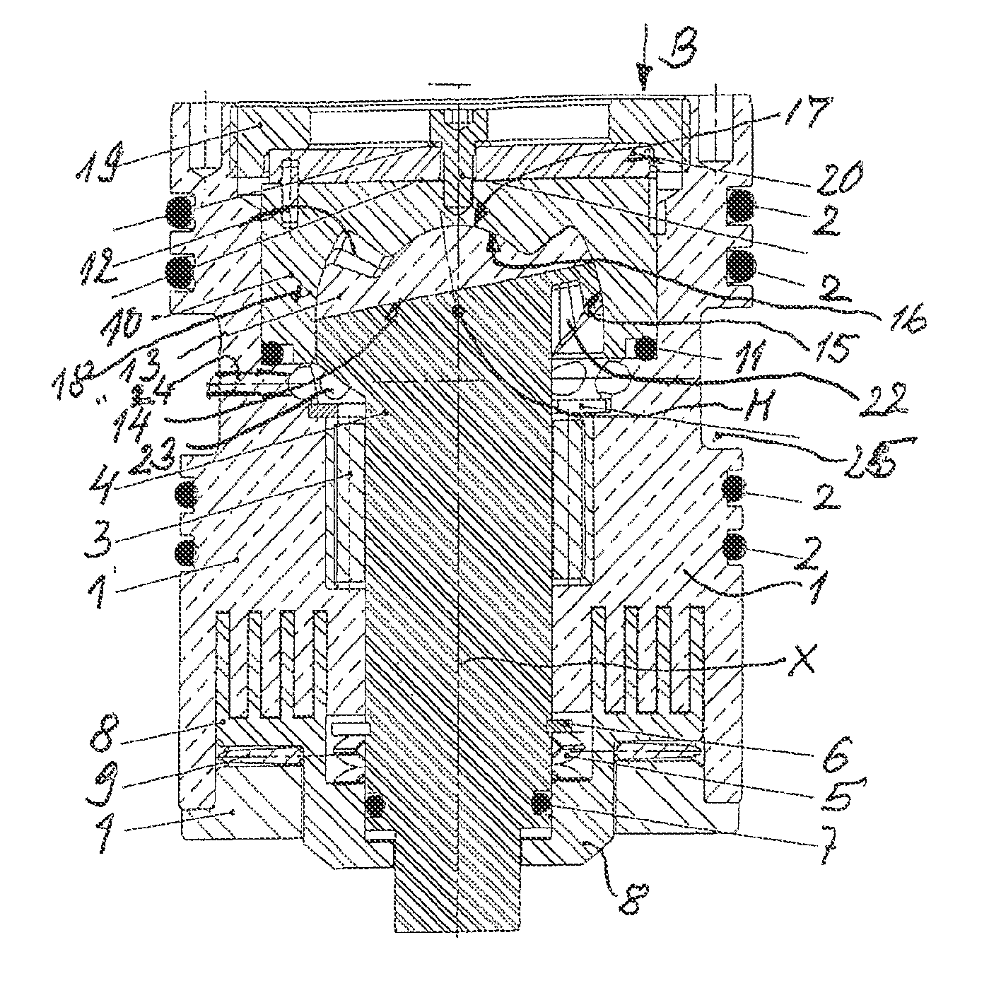
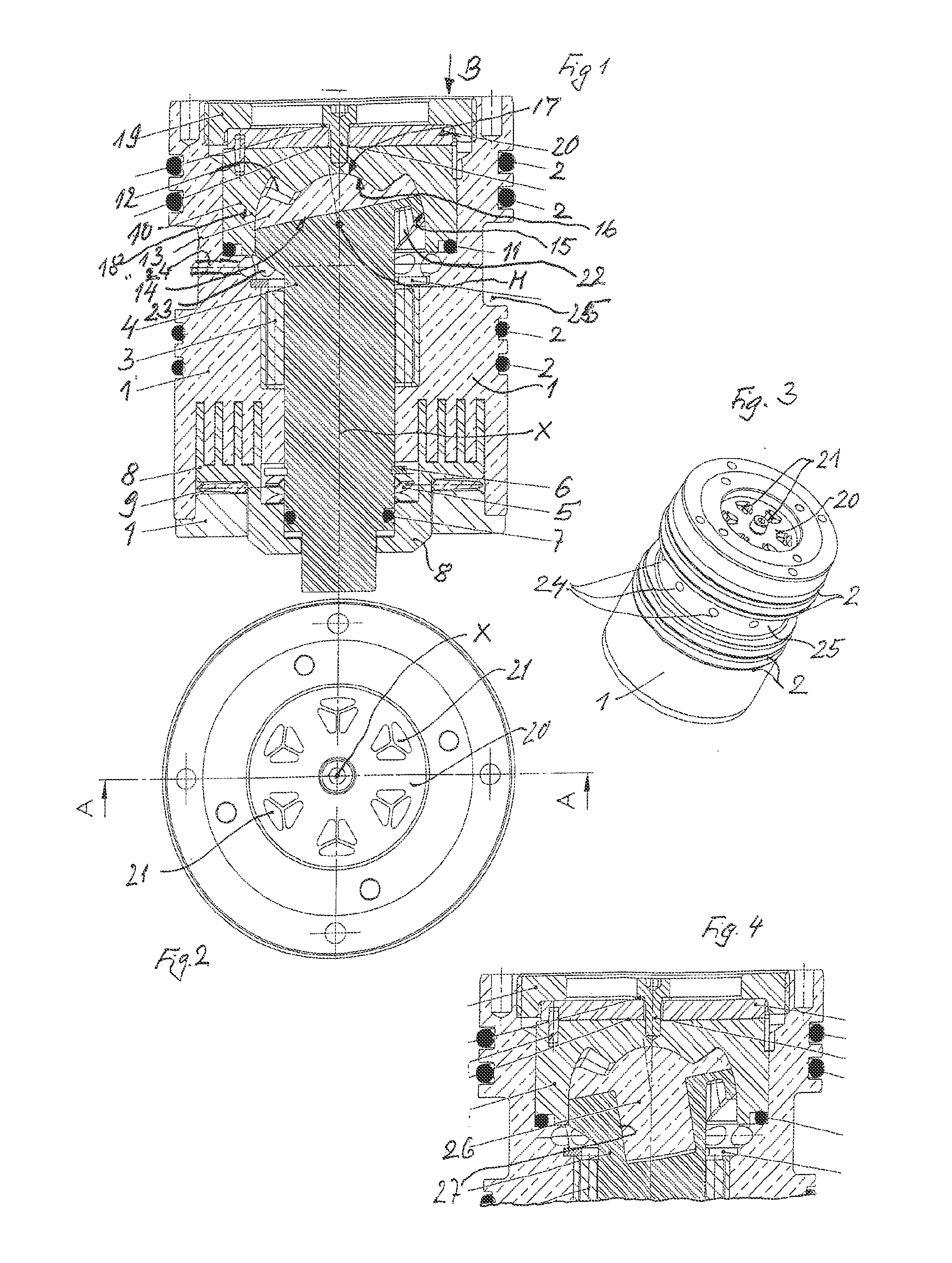
[0033]In FIG. 1, an exemplary embodiment of the invention is shown in longitudinal section and is then also shown in perspective in FIG. 3. This is a machine which depending on its use can be used as a pump or motor for liquid or gaseous media, and as can be seen particularly from FIG. 3, the cross section of the mounting housing 1 is cylindrical, to enable inserting the machine into corresponding bores. Toward the bore wall, not shown, O-rings 2 form the requisite sealing off of the mounting housing 1 from the part receiving the machine, such as a pipeline or also a bore in an apparatus that receives this machine. In this mounting housing 1, a shaft 4 is rotatably supported via a radial bearing 3, and via a spring means embodied as a leaf spring 5 and a securing ring 6, the shaft is lightly loaded in the axial direction and is correspondingly displaceable. For sealing purposes, an O-ring 7 is used between the shaft 4 and a housing insert 8; this ring is braced on the mounting housi...


PUM


Abstract

A pump or motor for fluid or gaseous media comprising a shaft (4), which faces a working part (13) and has a common inclined sliding surface (14) with the same, whereby the working part (13) limiting the pump working spaces (12) wobbles in a positionally fixed housing (10).

Description

CROSS-REFERENCE TO RELATED APPLICATIONS[0001]This application is a divisional of co-pending U.S. application Ser. No. 12 / 531,186 filed on Dec. 31, 2009, which is a national phase application under 35 U.S.C. § 371 International Application No. PCT / DE2008 / 000425 filed on Mar. 13, 2008, which claims priority to German Application No. 102007012574.9 filed on Mar. 13, 2007 and German Application No. 102008009694.6 filed Feb. 18, 2008, the entire contents of all of which are incorporated herein by reference.BACKGROUND OF THE INVENTION[0002]In a known machine of this type (German published patent application DE-OS 42 41 320), the working part is driven via the shaft, and in the manner like a machine with spur toothing, the working parts between the work faces are reduced or increased in size for pumping the medium. Conversely, such a machine can also act as a motor, in that medium is pumped under pressure into the work chambers and by increasing the size of the work chambers generates a dr...

Claims


Application Information

Patent Timeline
29 Aug 2013
Publication
US20130224056A1
IPC
F01C1/00
CPC
F01C1/084; F01C3/085; F01C1/00; F04C15/068; F04C2240/60; F01C21/18
Inventors
ARNOLD, FELIX; SKRYNSKI, EVGENIJ