Buckle System and Mounting Bracket

a buckle system and mounting bracket technology, applied in the field of buckle systems, can solve the problems of large profile and bayonet couplings, and achieve the effects of reducing profile, strong and low profile, and lessening the profile of the buckle system

Inactive Publication Date: 2013-09-05
SZELLOS DAVID
View PDF12 Cites 2 Cited by
  • Summary
  • Abstract
  • Description
  • Claims
  • Application Information

AI Technical Summary

Benefits of technology

[0014]One advantage of the present invention is that the strength of bayonet mounts may be incorporated into the described embodiments, while a projecting feature of the mounting clip is able to engage a slot in the mounting bracket in a manner that lessens the profile of the buckle system. A hook is provided in the buckle system that secures to the slot through a rotation of the latching mechanism around an axis that is parallel to the insertion of the tongue into the bracket body. This coupling is both strong and low in profile. A further reduction in profile is enabled by the provision of the groove in the bracket body itself to allow rotation of the latching mechanism, about the tongue position, once inside the groove.
[0015]Another advantage of the buckle system is the ease of mating the mounting clip with the mounting bracket. The coupling is exploited to improve mating the two pieces together. In operation, the tongue of the mounting clip is guided into the groove in the mounting bracket. Once the tongue is slideably received into the groove, the hook of the mounting clip is inserted into the slot of the mounting bracket to latch the two components together. These two complementary pairs mate the mounting clip to the mounting bracket and provide strength to the buckle system.
[0016]Strength in the buckle system is also achieved through the complementary shapes of the mounting clip and mounting bracket. Matching the shapes of the coupling pieces allows the forces exerted on the mounting clip and mounting bracket to be shared across the entire volume of the buckle system.
[0017]Yet another advantage of the present invention is the resistance to separation of the mounting clip from the mounting bracket in any single direction. Because separating the mounting clip from the mounting bracket requires two separate, independent movements, i.e. a lifting of the hook from the slot in one direction and the sliding of the tongue out of the groove in a separate and different direction, a force in any one direction will not separate the two components. Accordingly, as the direction for tongue insertion into the groove and the orientation of the axis of rotation of the protruding hook are parallel, additional strength against torque perpendicular to the base of the tongue can be provided in the construction of the mounting clip and mounting bracket. Furthermore, the independent nature of the two separating motions is enhanced as the slot in the mounting bracket is distinct and independent from the groove and therefore the forces acting on either the slot or the groove are at different locations on the bracket body.
[0018]While the buckle system may be used in a number of different embodiments, the inventor has appreciated that a strong, low-profile buckle system is especially desirable for use with computers and, more particularly, portable media devices. In a preferred embodiment, the inventor has appreciated that a low-profile mounting bracket could be incorporated with a watch strap such that, when coupled to a portable media player, the mounting bracket and portable media player combination may be worn as a bracelet or a watch.
[0019]Further and other features of the invention will be apparent to those skilled in the art from the following figures and detailed description of the embodiments thereof.

Problems solved by technology

Bayonet couplings have this feature but suffer from a large profile.

Method used


Image

  • Buckle System and Mounting Bracket
  • Buckle System and Mounting Bracket
  • Buckle System and Mounting Bracket

Examples


Embodiment Construction

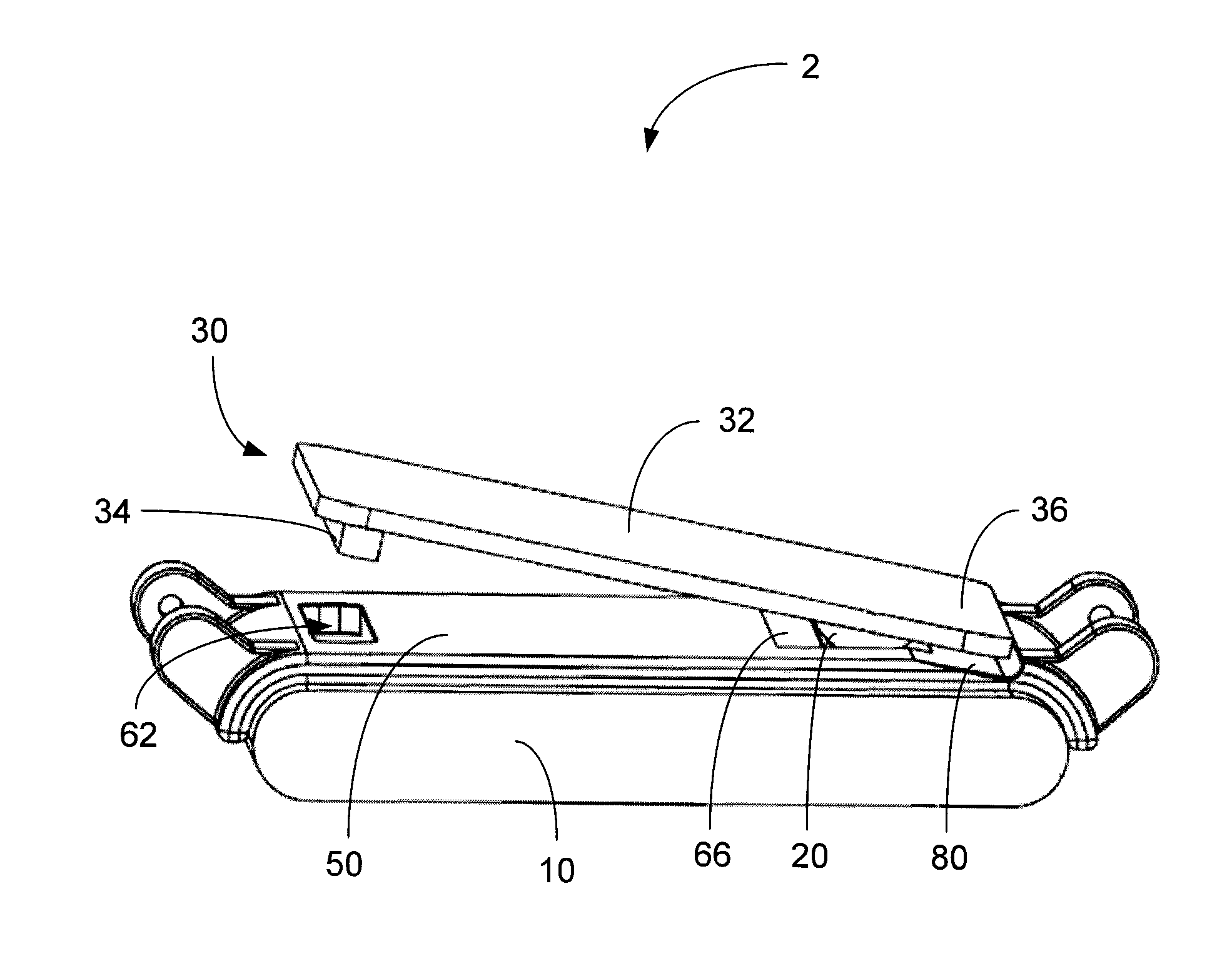
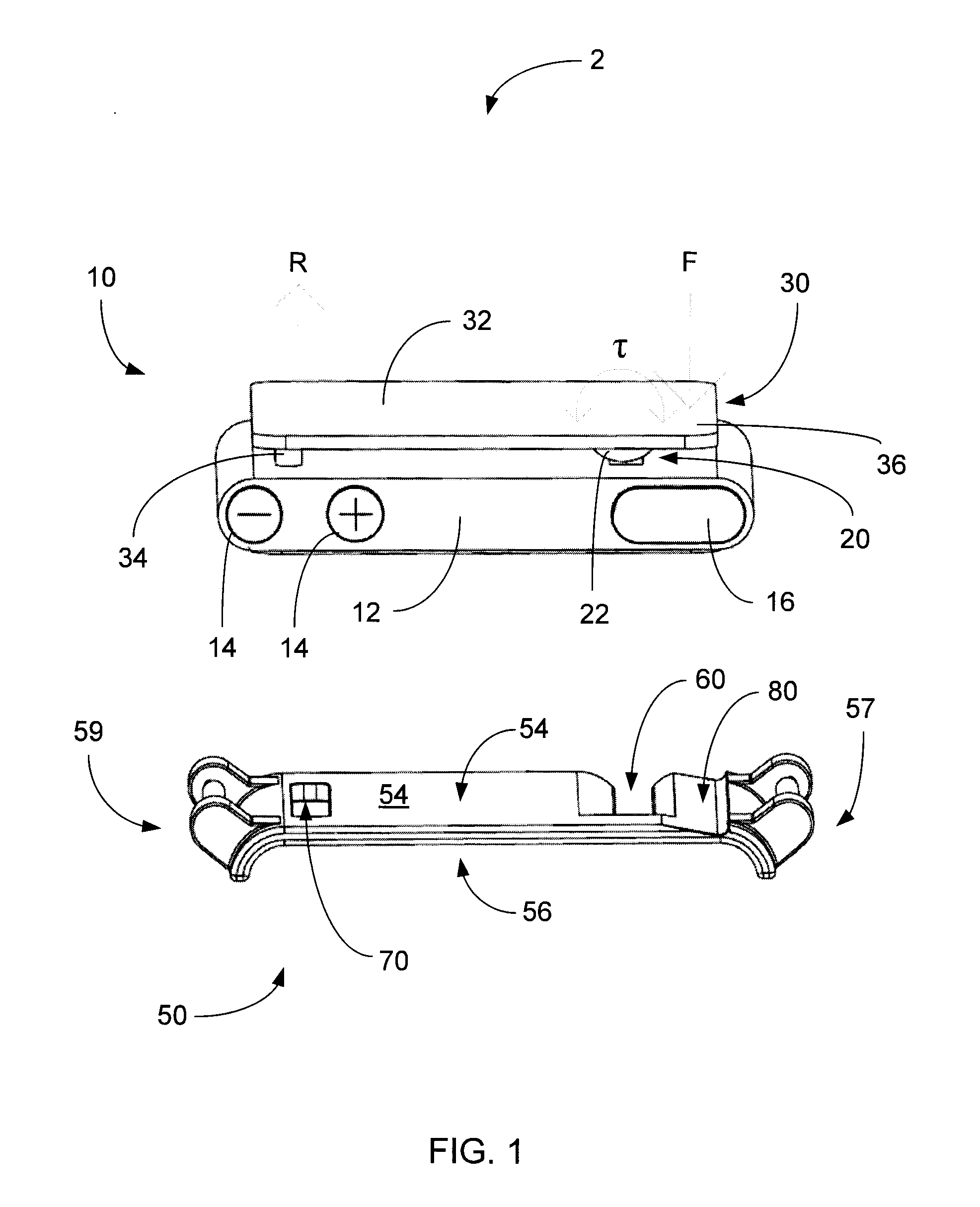
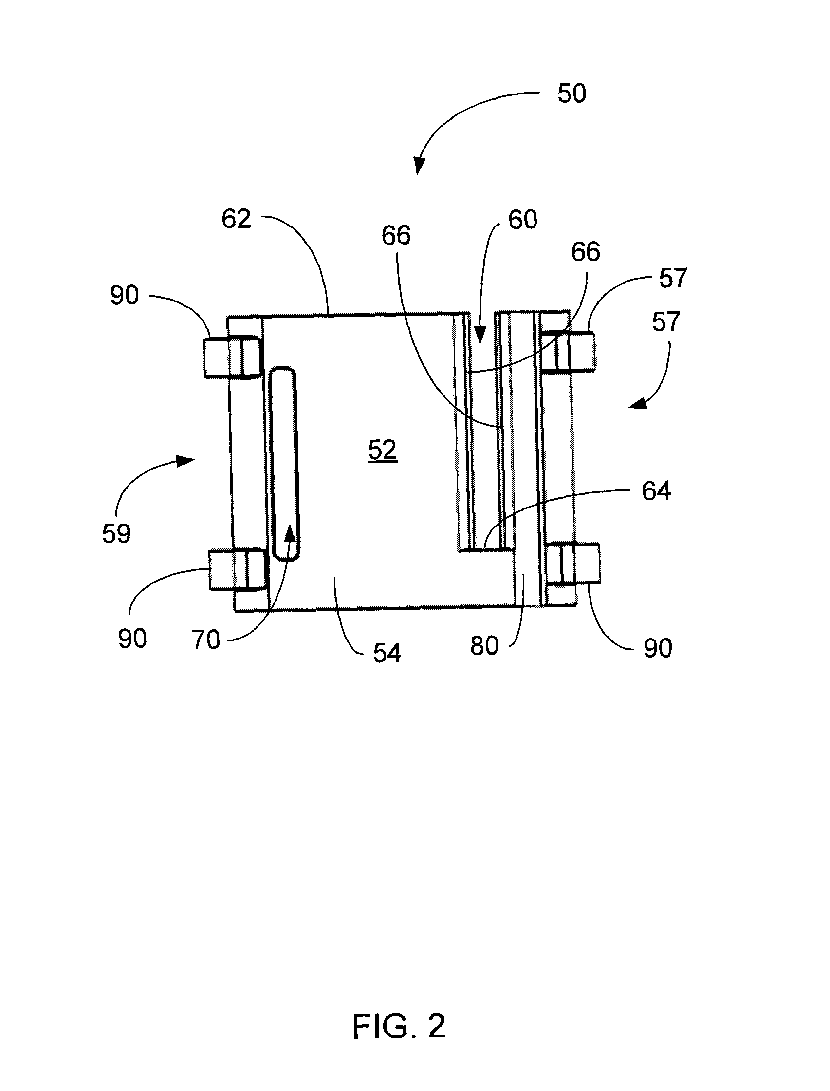
[0028]An exploded view of a buckle system 2 is provided in FIG. 1. The buckle system 2 is formed by a mounting clip 10 mating with a mounting bracket 50.

[0029]The mounting clip 10 is configured with a clip body 12, a tongue 20 and a latching mechanism 30. The clip body 12 is mechanically coupled to the latching mechanism 30 by the tongue 20. For example, at least part of the tongue 20 may be formed as a joint connecting the latching mechanism 30 to the clip body 12.

[0030]In a preferred embodiment, the tongue 20 connecting the latching mechanism 30 to the clip body 12 is spaced towards one end of the latching mechanism 30. The latching mechanism 30 is configured with a lever 32 and a hook 34. The lever 32 is operable to rotate or pivot about an axis or a fulcrum (not shown) defined by the tongue 20. A tongue end 36 is on one side of the lever 32 and the hook 34 is spaced towards the other side of the lever 32, with the tongue 20 coupling to the lever 32 between the tongue end 36 and ...


PUM


Abstract

A buckle system is provided having a mounting bracket and a mounting clip. The mounting bracket includes a bracket body, a slot and a groove and has a first surface and a second surface opposite the first surface, with the slot and the groove formed in the bracket body. The mounting clip includes a clip body, a latching mechanism and a tongue. The clip body is connected to the latching mechanism by the tongue, which is slid into the groove formed in the bracket body of the mounting bracket such that the latching mechanism is adjacent the first surface of the bracket body and the clip body is adjacent the second surface of the bracket body. A hook of the latching mechanism is received by the slot formed in the bracket body once the tongue of the mounting clip is slideably received into the groove of the mounting bracket.

Description

CROSS-REFERENCE TO RELATED APPLICATIONS[0001]The present application claims priority from U.S. application Ser. No. 12 / 889,944 filed Sep. 24, 2010 and U.S. application Ser. No. 12 / 891,883 filed Sep. 28, 2010, the teachings of which are hereby incorporated by reference in their entirety.FIELD OF THE INVENTION[0002]This invention relates to a buckle system and more particular to a buckle system having mounting clip and a mounting bracket.BACKGROUND OF THE INVENTION[0003]Buckles are well-known devices for connecting and securing objects. Many well-known buckle designs have been previously described.[0004]A simple patent by Payant (U.S. Pat. No. 3,999,251) illustrates the three parts of a buckle. Payant describes an invention with a belt tongue and a buckle bracket and a locking device.[0005]Coupling patents that describe a tongue passing into a bracket include Mallek (U.S. Pat. No. 5,865,562), Mcleod (U.S. Patent Publication No. 2010 / 0122411) and Levine (U.S. Pat. No. 4,886,297). Malle...

Claims


Application Information

Patent Timeline
Patent Type & Authority Applications(United States)
IPC IPC(8): A44B11/25
CPCA44B11/258F16M11/041Y10T24/407F16M13/04A44B11/25F16M13/00
Inventor SZELLOS, DAVID
Owner SZELLOS DAVID
Why Eureka
Try Eureka