
Butterfly Valve Disc to Attain Accelerated Flow

a technology of butterfly valve and disc, which is applied in the direction of valve arrangements, mechanical equipment, engine components, etc., can solve the problems of adding to the overall weight of the accessory, and achieve the effect of enhancing the shape, configuration and structure of the disc, and accelerating the flow of granular materials

Active Publication Date: 2013-09-05
BULK TANK
View PDF6 Cites 1 Cited by
  • Summary
  • Abstract
  • Description
  • Claims
  • Application Information

AI Technical Summary

Benefits of technology

The invention is a new shape for the disc of a butterfly valve that improves the flow of granular materials, such as sand or salt, from tank trailers. This disc design helps to reduce the time and noise that is associated with unloading these materials. The unique shape of the disc also improves the flow of granular materials through the valve, which reduces the amount of material that needs to be moved. Additionally, using a lighter material like aluminum for the disc reduces the weight of the entire accessory.

Problems solved by technology

Furthermore, making the disc of the butterfly valve, and particularly its arcuate disc, of aluminum, adds to a lesser weight for the overall structure of the accessory, particularly during its installation and removal.

Method used


Image

  • Butterfly Valve Disc to Attain Accelerated Flow
  • Butterfly Valve Disc to Attain Accelerated Flow
  • Butterfly Valve Disc to Attain Accelerated Flow

Examples


Embodiment Construction

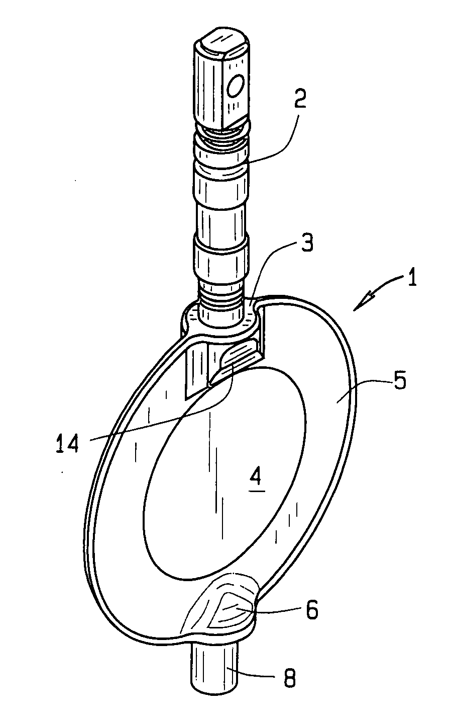
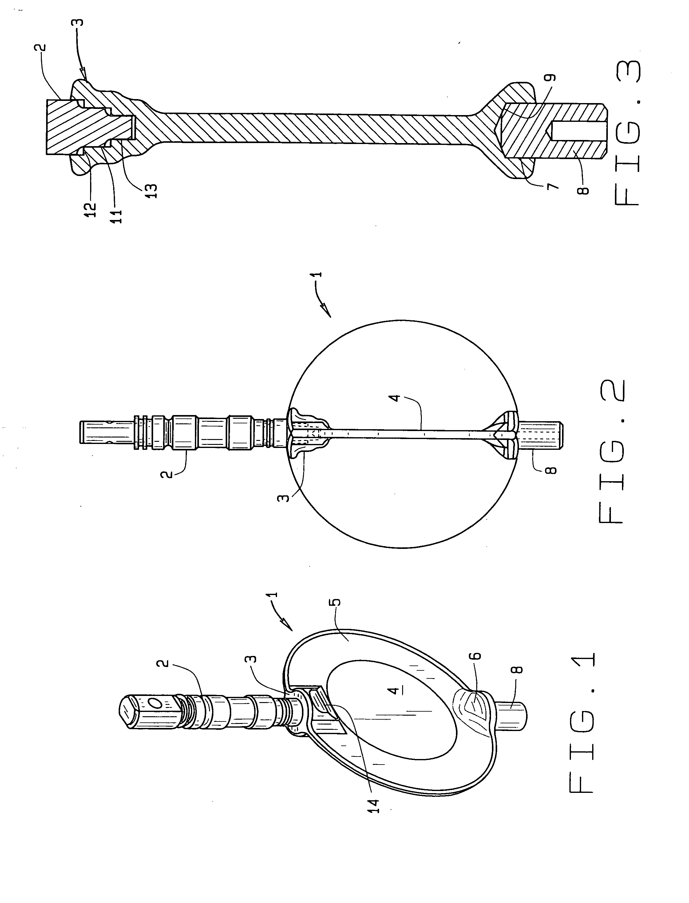
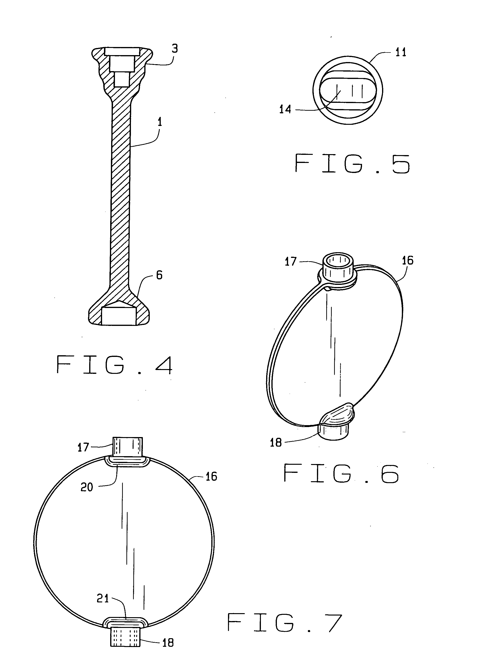
[0090]In referring to the drawings, and in particular FIGS. 1 and 2, the shaped disc 1 of this invention is disclosed, showing having its operative shaft 2 connected therewith, through its integral socket 3, as can be noted. Initially, this disc is a thin line disc, and therefore, because it has lesser structure, and surface area, when it is opened, for allowing accelerated granular material to flow from the butterfly valve in which it mounts, and as can be seen in FIG. 2, it has a very thin dimension, which provides greater open capacity in the cross-section to allow for flow of the granular material from the tank trailer, through the butterfly valve, and into a storage or conveying area, as known on the art.

[0091]As can be seen, the disc has a thickest configuration at approximate its central location, as at 4, and then tapers, as at 5, to its outer edge, where it has its thinnest configuration, as can be noted.

[0092]The bottom edge of the disc has an integral socket 6, which has ...


PUM


Abstract

An improved disc for a butterfly valve having reduced structure within the bore of the valve, so as to minimize obstruction to the flow of granular material therethrough. Accelerated flow of granular material through the valve is obtained because of the thin dimensions of the butterfly valve. The modified disc includes upper and lower sockets, most of its structure is outside the perimeter of the disc. The disc may be of arcuate shape.

Description

CROSS REFERENCE TO RELATED APPLICATION[0001]This non-provisional patent application claims priority to the provisional patent application having Ser. No. 61 / 634,580, having filing date Mar. 2, 2012, which claims priority to the design patent application having Ser. No. 29 / 373,130, having filing date Mar. 4, 2011; this application claims the benefits of and is a continuation-in-part of the design patent application having Ser. No. 29 / 374,020, having filing date Jun. 23, 2011; and this application claims the benefits of and is a continuation-in-part of the utility patent application having Ser. No. 13 / 506,246, having filing date Apr. 6, 2012, now Publication No. US 2012-0241657 A1, which claims priority to the provisional patent application having Ser. No. 61 / 517,200, having filing date Apr. 18, 2011; all of said applications being owned by a common assignee.FIELD OF THE INVENTION[0002]This invention relates to a disc for a butterfly valve that is structured to aid in accelerating the...

Claims


Application Information

Patent Timeline
Patent Type & Authority Applications(United States)
IPC IPC(8): F16K1/22
CPCF16K1/222F16K1/22F16K1/224
Inventor SISK, DAVID E.
Owner BULK TANK
Learn More