Control of Multi-Hulled Water Craft

a multi-hulled water craft and control technology, applied in the field of watercraft, can solve the problem of water craft body experiencing corresponding roll or pitch

Active Publication Date: 2013-09-12
NAUTI CRAFT PTY LTD
View PDF5 Cites 4 Cited by
  • Summary
  • Abstract
  • Description
  • Claims
  • Application Information

AI Technical Summary

Benefits of technology

[0018]When the water craft has one or two pairs of laterally spaced water engaging means, alternatively the compression chamber of the front left pitch support ram may connected to the compression chamber of the front right pitch support ram by a front pitch compression conduit so as to form the front pitch compression volume, and the compression chamber of the back left pitch support ram may be connected to the compression chamber of the back right pitch support ram by a back pitch compression conduit so as to form the back pitch compression volume, the pitch support rams thereby providing substantially no roll stiffness to resist roll motions of the body portion of the water craft. The water craft may further include a respective roll ram for each water engaging means, wherein each roll ram includes at least a compression chamber, the compression chambers of the front left and back left roll rams forming at least one left roll compression volume and the compression chambers of the front right and back right roll rams forming at least one right roll compression volume.
[0023]In an alternative arrangement having at least one left roll ram forming part of at least one left roll compression volume and at least one right roll ram forming part of at least one right roll compression volume, a fluid pressure control system may be provided including a fluid pump and at least one valve (to selectively communicate the fluid pressure control system with at least one of the left or right roll compression volumes) to thereby enable control of the roll attitude of the body.
[0024]In an alternative arrangement having at least one left roll ram forming part of at least one left roll compression volume and at least one right roll ram forming part of at least one right roll compression volume, a body roll conduit may be connected between the at least one left roll compression volume and the at least one right roll compression volume, the body roll conduit including a body roll device dividing the body roll conduit into a body roll conduit left portion and a body roll conduit right portion, the body roll device controlling the effective flow of fluid between the body roll conduit left and right portions. That is, the body roll device may control the flow of fluid through the body roll conduit left portion and the body roll conduit right portion, into and out of (or towards and away from) the left and right roll compression volumes.
[0025]In another arrangement, for each of said at least one forward water engaging means there may be provided two body pitch support rams being a forward pitch support ram and a rearward pitch support ram, each forward and rearward pitch support ram including a respective compression chamber, the forward pitch support ram compression chamber of said at least one forward water engaging means forming a front forward pitch volume and the rearward pitch support ram compression chamber of said at least one forward water engaging means forming a front rearward pitch volume, a front heave device being provided comprising a first cylinder and a second cylinder axially aligned with and larger in diameter than the first cylinder, a piston rod assembly located within and axially aligned with the first and second cylinders and including at least a piston on one end located within the second cylinder, the piston rod assembly forming a first chamber in the first cylinder and forming a second chamber and a third chamber in the second cylinder, the first and second chambers varying in volume in the same direction with motion of the piston rod assembly and in the opposite direction to the third chamber, the first chamber being connected to the front forward pitch volume and the second chamber being connected to the second chamber, the third chamber thereby displacing a fluid volume substantially equal to the sum of the fluid volume displaced by (into or out of) the first and second chambers with motion of the piston rod assembly, the third chamber being connected to the front portion of the body pitch conduit. To clarify the functionality of the construction of the heave device, when the piston rod assembly moves such that the first chamber increases in size, the second chamber also increases in size and the third chamber decreases in size.
[0034]The water craft may further include a fluid pressure control system including a fluid pump and at least one valve (to selectively communicate the fluid pressure control system with at least one of the front or back pitch compression volumes) to thereby enable control of the pitch attitude of the body.

Problems solved by technology

However as waves are encountered, the average surface of the water does not remain level, causing the body of the water craft to experience corresponding roll or pitch.

Method used


Image

  • Control of Multi-Hulled Water Craft
  • Control of Multi-Hulled Water Craft
  • Control of Multi-Hulled Water Craft

Examples


Embodiment Construction

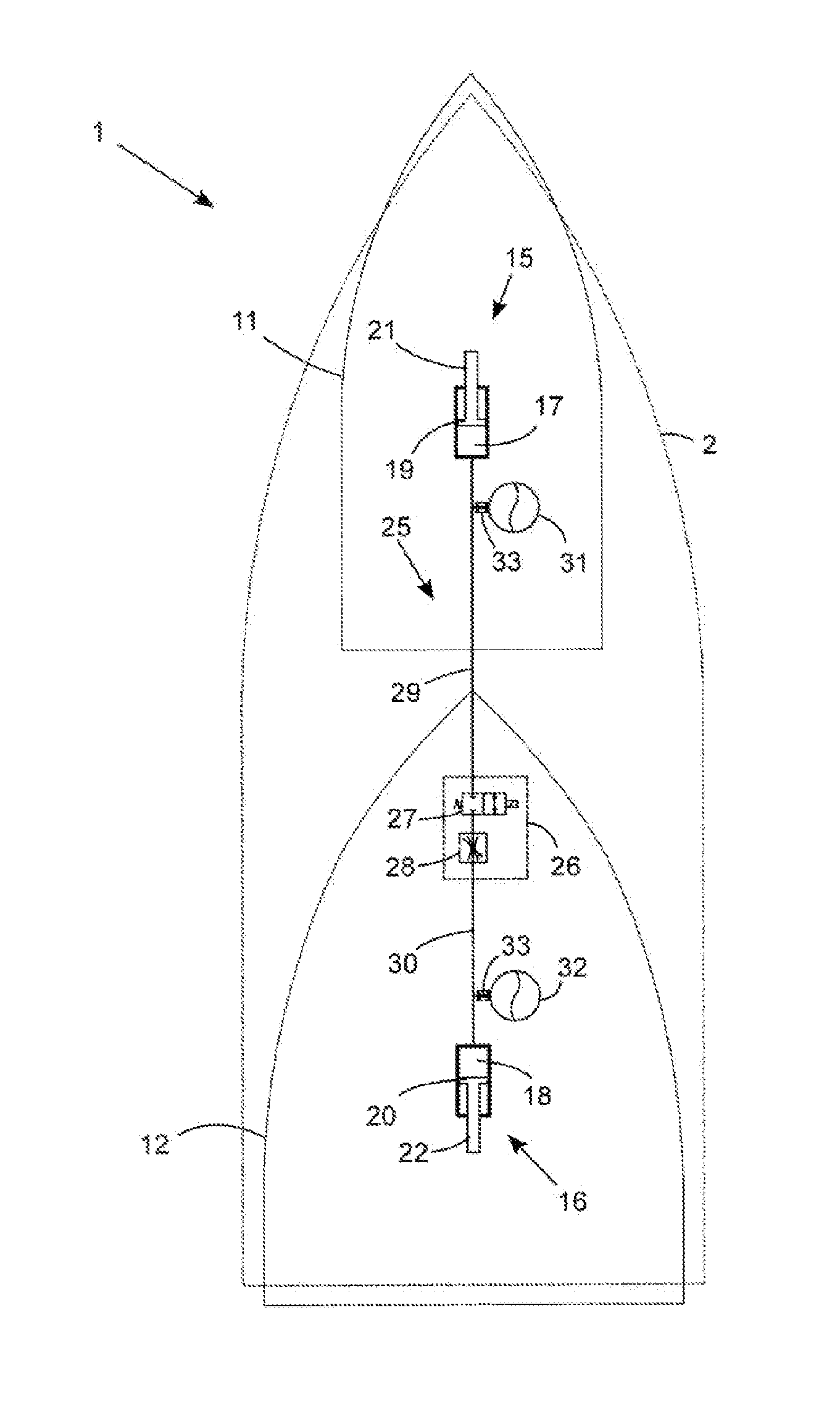
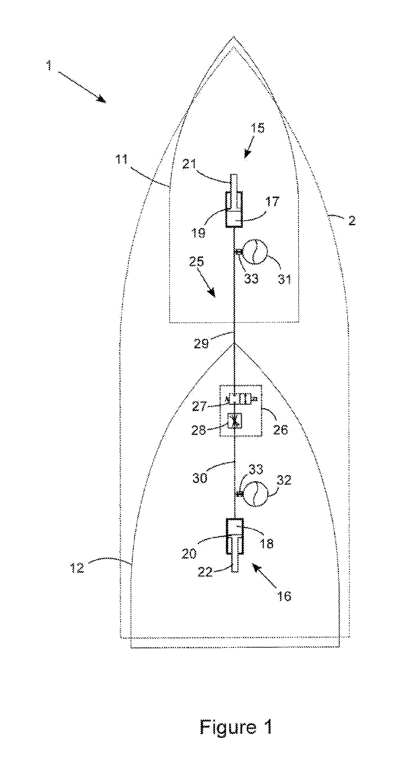
[0053]Referring initially to FIG. 1, there is shown a water craft 1 in accordance with an embodiment of the present invention. The water craft 1 includes a body portion or body 2, a front water engaging means 11, and a back water engaging means 12. Each water engaging means is located relative to the body by locating geometry (not shown) which permits generally vertical motion of the water engaging means with respect to the body. The locating geometry (i.e. locating means) for each water engaging means generally comprises one or more arms extending between and being pivotally connected to the body and the water engaging means. Each arm can have a number of shapes and types, for example if only one or two arms are used, they can be V-shaped (like a wishbone) or rectangular or any shape and form including box section portions to provide strength and fit in the space available for all desired positions of the water engaging means. The locating means can include any linkages commonly us...


PUM


Abstract

A water craft has a body portion and at least two water engaging means. The body portion is at least partially suspended above the at least two water engaging means by a suspension system, and locating means are provided to connect each water engaging means to the body portion to permit substantially vertical and pitch direction motions of the water engaging means relative to the body. The suspension system includes at least one front pitch support ram and at least one back pitch support ram, the front and back pitch support rams providing support for at least a portion of the body relative to the at least two water engaging means.

Description

[0001]This application is a continuation of Patent Cooperation Treaty Patent Application PCT / AU2011 / 000557 filed May 16, 2011, which is incorporated herein by reference.TECHNICAL FIELD[0002]The present invention relates to water craft having a body supported above multiple hulls, and more particularly to the control of the attitude of the body above those hulls.BACKGROUND ART[0003]It is known to provide a single-hull displacement type water craft which is capable of moving relatively efficiently through a body of water at low speed. However, as the speed increases, it is known that craft with multiple long slender hulls (such as catamarans) provide improved efficiency. As speeds increase further it is known to provide planing-type water craft which significantly reduce the volume of water displaced when planing and therefore provide increased efficiency at high speeds. The hulls of planing water craft are generally wider (especially towards the rear) and shorter than displacement wa...

Claims


Application Information

Patent Timeline
Patent Type & Authority Applications(United States)
IPC IPC(8): B63B1/14
CPCB63B1/14B63B39/00B63B39/005B63B27/14B63B27/30B63B39/04B63B2001/145B63B2017/0072B63B21/00B63B39/10G05D1/0875B63B2039/105B63B1/22B63B1/10
Inventor HEYRING, CHRISTOPHER BRIANCATONI, JOHN GERARDMONK, RICHARD
Owner NAUTI CRAFT PTY LTD
Why Eureka
Try Eureka