Packaging case

a packaging case and case body technology, applied in the field of packaging cases, can solve the problems of high material cost, achieve the effects of reducing material cost and transportation cost, effective preventing cracks, and thin thickness

Inactive Publication Date: 2013-09-12
FOXLINK IMAGE TECH
View PDF0 Cites 20 Cited by
  • Summary
  • Abstract
  • Description
  • Claims
  • Application Information

AI Technical Summary

Benefits of technology

[0007]As described above, the fastening shell and the buffering elements are designed separately, so the buffering elements fully afford an external force struck on the buffering elements for effectively preventing cracks being caused between each of the buffering elements and the fastening shell. Accordingly, the fastening shell is designed with a thinner thickness to lower a material cost and a transportation cost. Furthermore, the buffering elements assembled to the fastening shell are changeable to make the buffering elements dismountably inserted into the insertion holes of the fastening shell properly and simply. As a result, a better buffering function of the packaging case is realized to improve a packing quality of the packaging case so as to assure satisfactory degrees of customers.

Problems solved by technology

However, in order to protect the product 3, the packaging case 4 is usually designed with a thicker thickness so that results in a higher material cost.

Method used


Image

  • Packaging case
  • Packaging case
  • Packaging case

Examples


Embodiment Construction

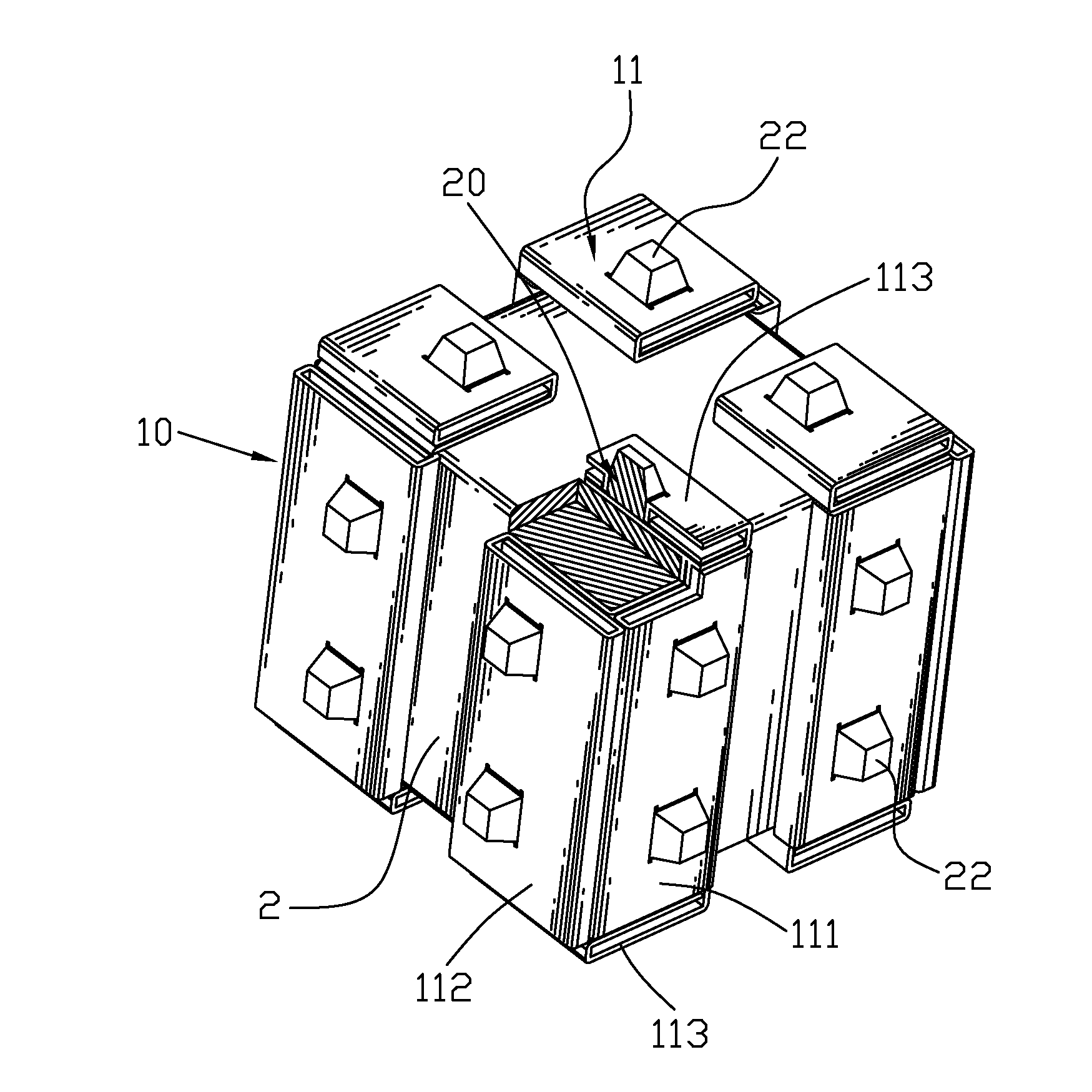
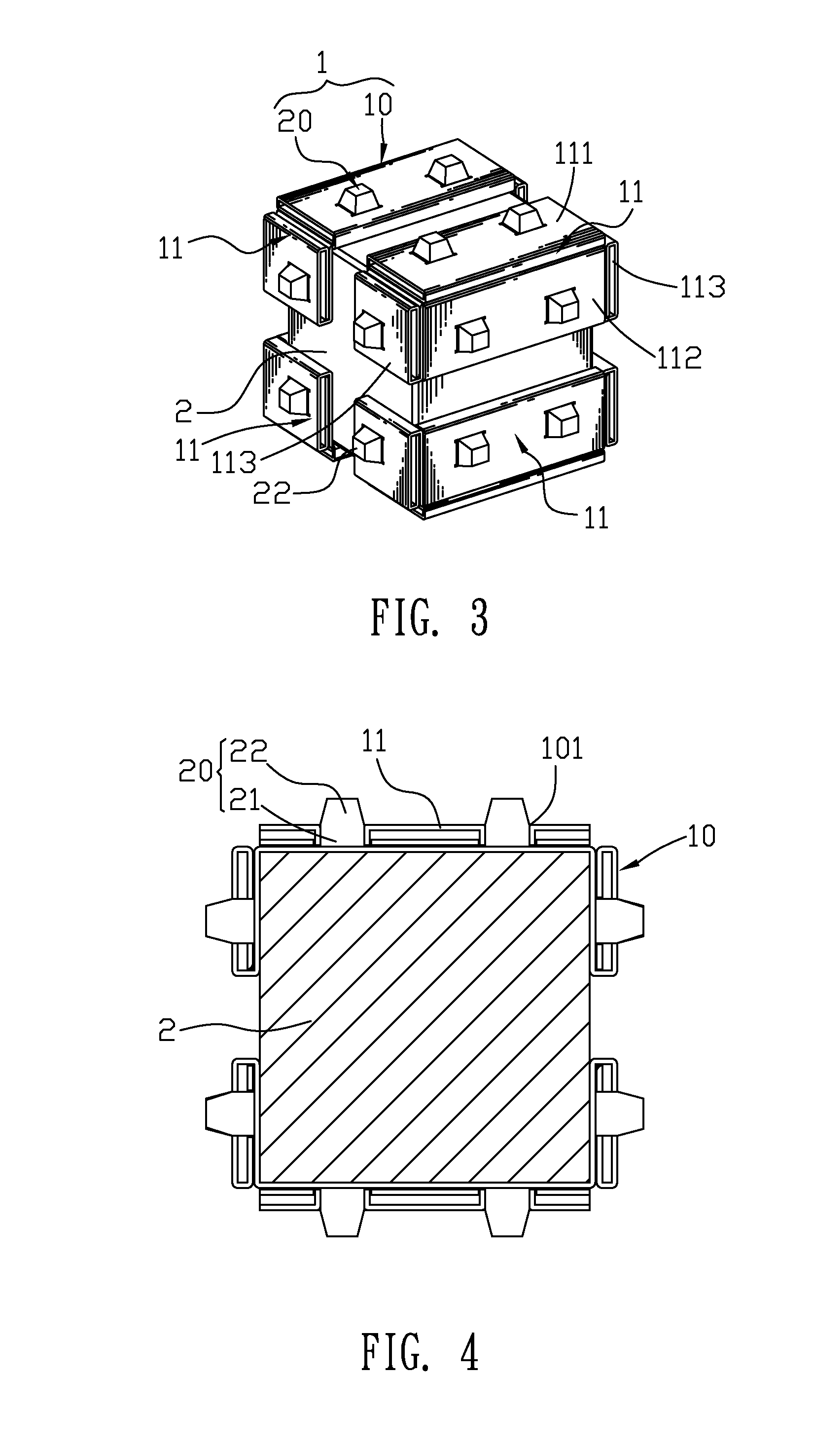
[0014]With reference to FIG. 3 and FIG. 4, a packaging case 1 in accordance with the present invention is shown. The packaging case 1 adapted for packing a cubic article 2 includes a fastening shell 10 and a plurality of buffering elements 20.

[0015]Referring to FIG. 3, FIG. 4 and FIG. 5, the fastening shell 10 is divided into four shells 11. Each shell 11 has a rectangular first wall 111, a rectangular second wall 112 perpendicular to the first wall 111, and two square third walls 113 connecting with the first wall 111 and the second wall 112. A receiving space (not shown) is accordingly formed among the first wall 111, the second wall 112 and the two third walls 113. Each of the first wall 111, the second wall 112 and the two third walls 113 defines at least one insertion hole 101.

[0016]Referring to FIG. 5, the fastening shell 10 is preferably made of a hollow sandwich material so as to lower a material cost and make the fastening shell 10 lighter for facilitating the fastening she...


PUM


Abstract

A packaging case adapted for packing an article therein includes a fastening shell and a plurality of buffering elements. Each wall of the fastening shell defines at least one insertion hole. The buffering elements are dismountably inserted into the insertion holes of the fastening shell with tops thereof projecting out of the insertion holes. The fastening shell and the buffering elements are designed separately, so the buffering elements fully afford an external force struck on the buffering elements for effectively preventing cracks being caused between each buffering element and the fastening shell. Accordingly, the fastening shell is designed with a thinner thickness to lower a material cost and a transportation cost. Furthermore, the buffering elements assembled to the fastening shell are changeable to make the buffering elements dismountably inserted into the insertion holes properly and simply. So a better buffering function of the packaging case is realized.

Description

BACKGROUND OF THE INVENTION[0001]1. Field of the Invention[0002]The present invention generally relates to a packaging case, and more particularly to a packaging case having a buffering function.[0003]2. The Related Art[0004]Referring to FIG. 1 and FIG. 2, a conventional packaging case 4 adapted for packing a rectangular product 3 therein has a rectangular first cover 41 and a rectangular second cover 42. A middle of a rear of the first cover 41 defines a first opening (not shown), and a middle of a front of the second cover 42 defines a second opening (not shown). A plurality of buffering ribs 43 protrude outward from a periphery of the first cover 41 and a periphery of the second cover 42. A plurality of buffering blocks 44 protrude outward from a front surface of the first cover 41 and a rear surface of the second cover 42. The buffering ribs 43 and the buffering blocks 44 are integrally molded with the first cover 41 and the second cover 42. One end of the product 3 is received ...

Claims


Application Information

Patent Timeline
Patent Type & Authority Applications(United States)
IPC IPC(8): B65D81/02
CPCB65D81/057B65D81/022
Inventor LIU, CHIN-TE
Owner FOXLINK IMAGE TECH
Why Eureka
Try Eureka