Device and method for constructing a laminar body comprising at least one position adjustable body defining the working area

a technology of a laminar body and a working area, which is applied in the direction of auxillary shaping apparatus, butter manufacture, additive mnaufacturing with solid and fluid, etc., can solve the problem of high technical complexity, constant increase of weight on the build platform as the building process progresses, and high stress on the guides and drives of the vertically moving build platform. problem, to achieve the effect of easy limitation of the size of the build spa

Active Publication Date: 2013-09-12
VOXELJET AG
View PDF8 Cites 61 Cited by
  • Summary
  • Abstract
  • Description
  • Claims
  • Application Information

AI Technical Summary

Benefits of technology

[0017]A body of this type then simulates an already discharged layer of free-flowing material, which prevents further discharge of material when this layer reaches the same level as the discharge opening of the discharging device. In this case, after all, the discharge opening has already been closed by the already discharged layer.
[0018]By designing the body or the build platform to be able to change at least the vertical position of the body in relation to the build platfor...

Problems solved by technology

However, the provision of a build container or build cylinder having a build platform which may be lowered vertically into the build container requires a high degree of technical complexity for sealing the build container wall against the build platform to prevent uncontrolled outflow of the particulate material through the gap between the build platform and the build container wall.
Another disadvantage of a lowerable build platform is the constantly increasing weight to be moved on the build platform as the building process progresses.
This results in high stresses on the guides and drives of a vertically moving build platform, in particular in the case of large build spaces and high feedstock densities.
However, such dosing-controlled and “intelligent” discharging devices have a relatively complex structure and are correspondingly expensive.
“Unintelligent” discharging devices of a simpler design, o...

Method used


Image

  • Device and method for constructing a laminar body comprising at least one position adjustable body defining the working area
  • Device and method for constructing a laminar body comprising at least one position adjustable body defining the working area
  • Device and method for constructing a laminar body comprising at least one position adjustable body defining the working area

Examples


Embodiment Construction

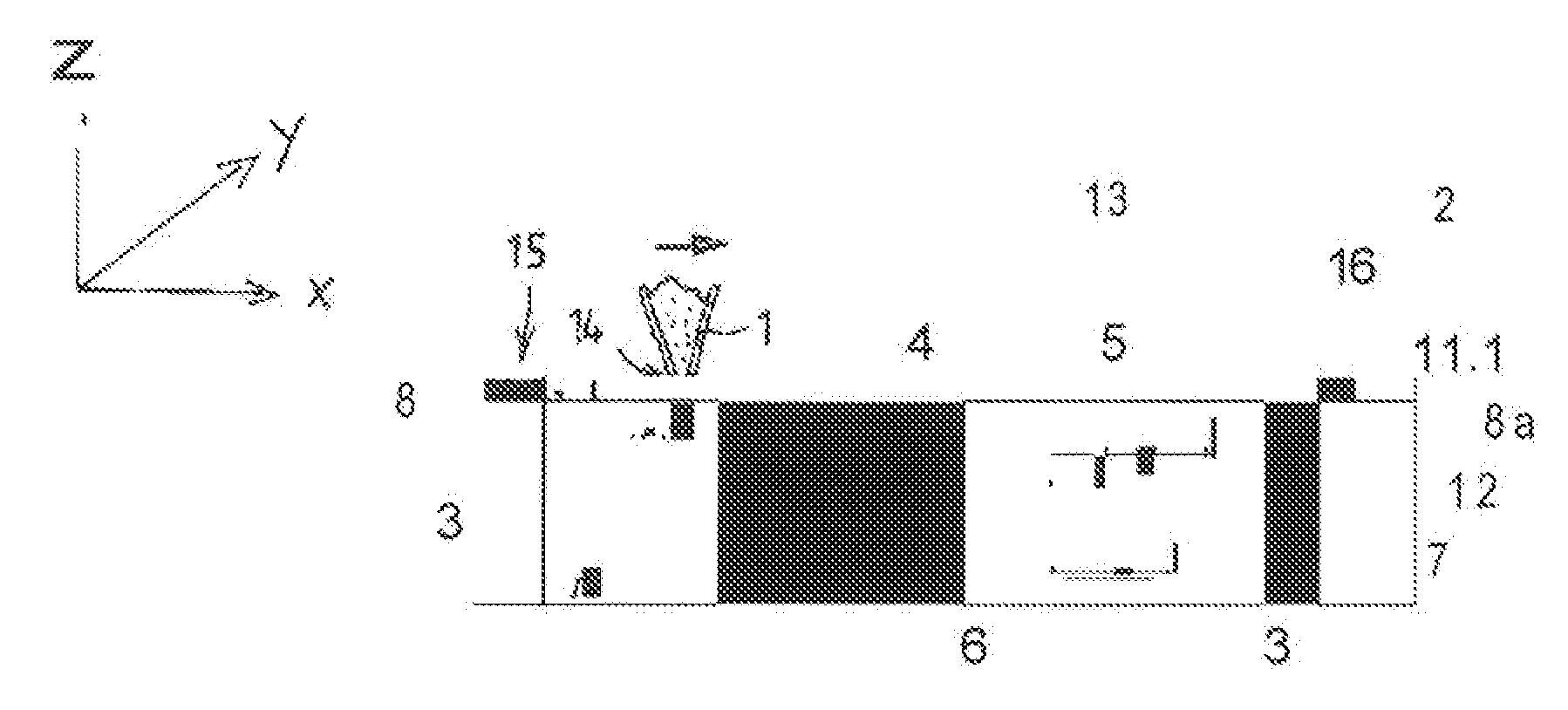
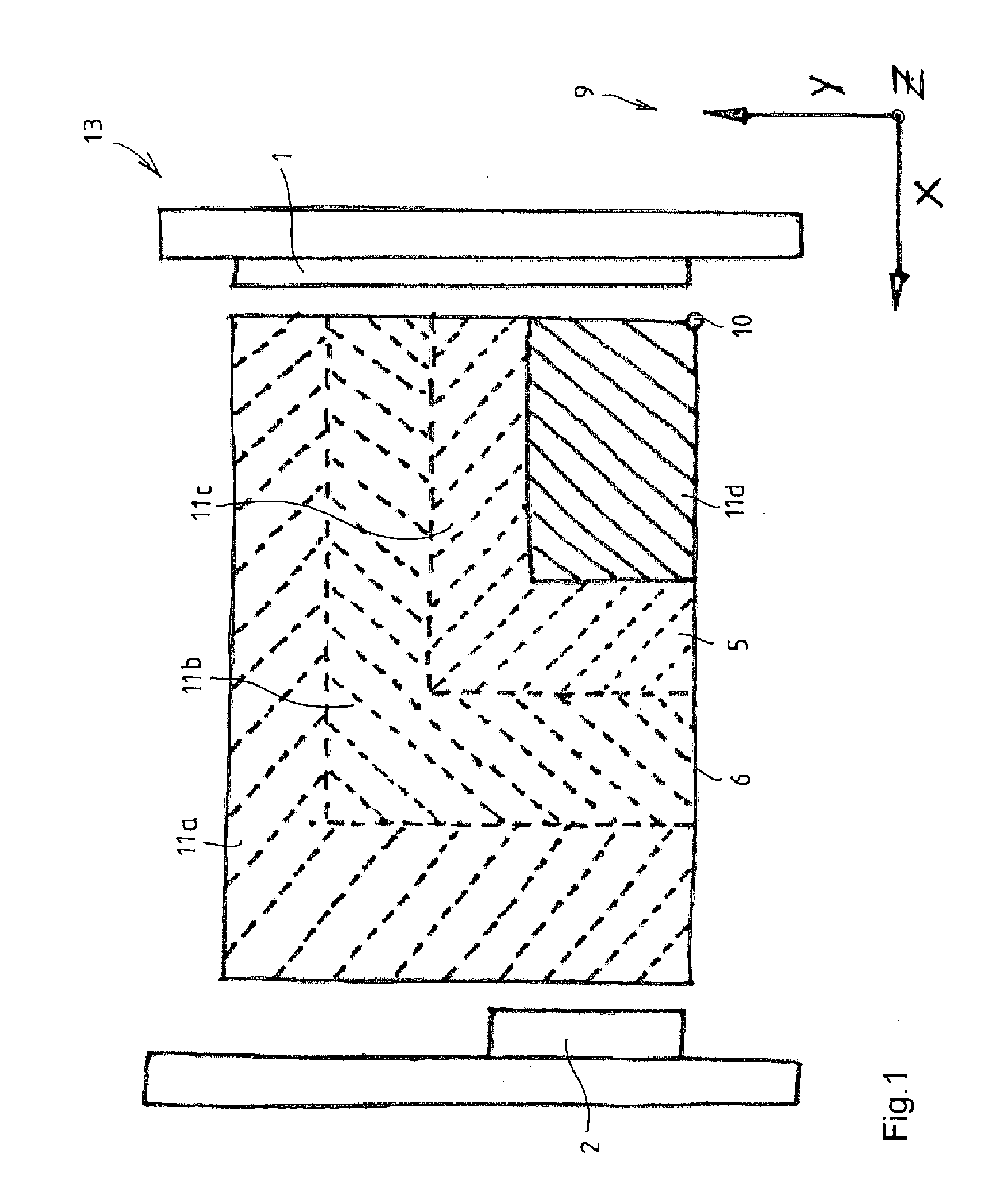
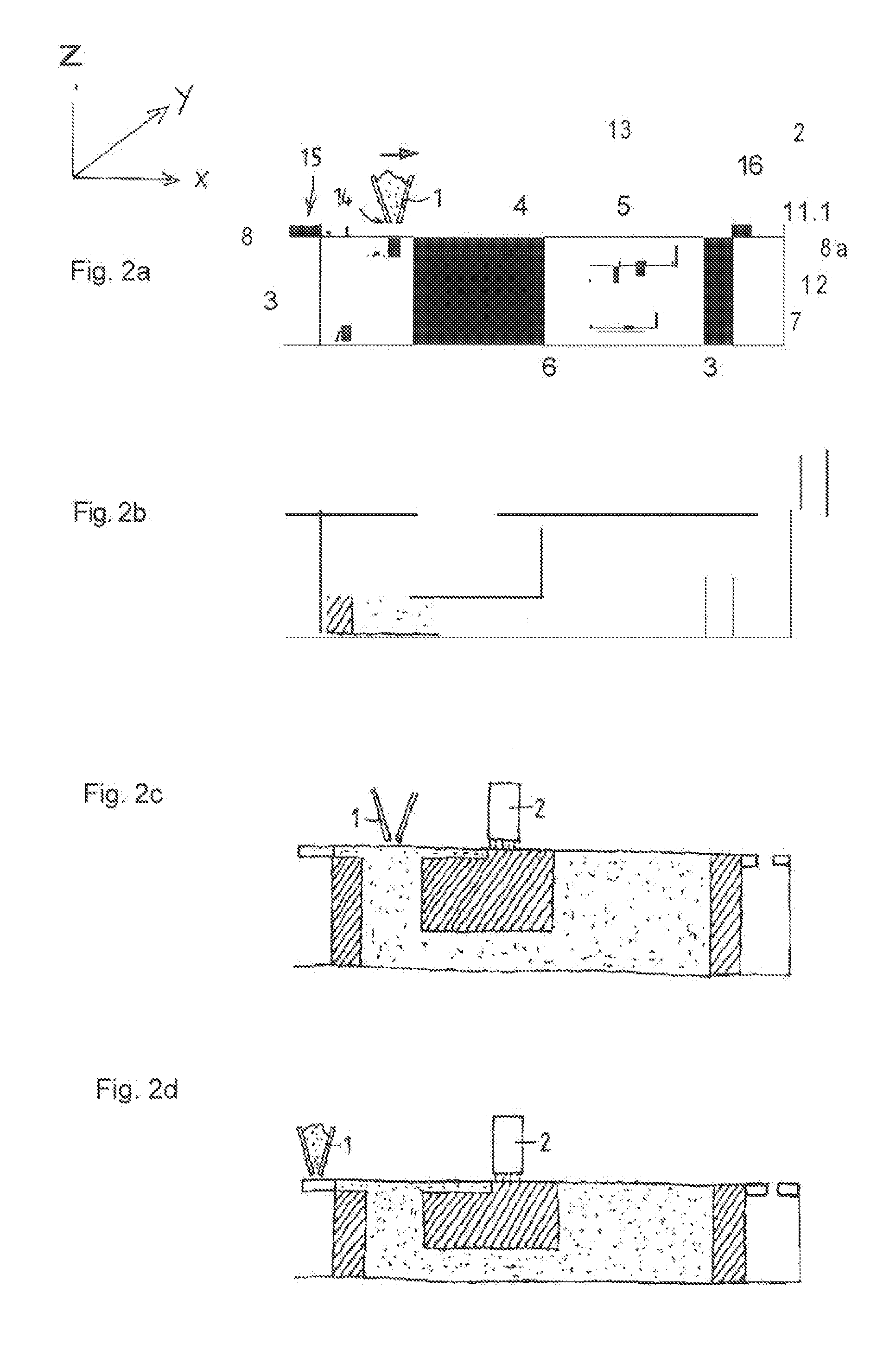
[0038]FIG. 1 shows a preferred embodiment of a device 13 for constructing a layer body 5 from a plurality of superimposed layers of, for example, powdered, initially loose, particulate material on a build platform 6 within a build space 11a through 11d.

[0039]Build spaces 11a through 11d of different sizes illustrated in FIG. 1 extend over a wide area in FIG. 1 parallel to build platform 8 in the horizontal X and Y directions, layer body 5 being constructed in the vertical Z direction, which is perpendicular to the drawing plane in FIG. 1.

[0040]Device 13 comprises a discharging device 1 which is movable back and forth over build space 11a through 11d in at least one discharge direction, in this case, for example, in the X direction and / or the Y direction, discharging device 1 having at least one discharge opening 14, which is not visible in this view and from which the particulate material, may be discharged in individual superimposed layers during the movement of discharging device...


PUM

PropertyMeasurementUnit
Areaaaaaaaaaaa

Abstract

The invention relates to a device (13) for constructing a laminar body (5) from a plurality of superimposed layers of free-flowing material, in particular particulate material, an a build platform (6) within a working area (11). The layers are solidified in locally predetermined regions by the action of binders and are joined together so that at least one moulded body (4) is formed by the solidified and joined regions of the layers. The device comprises a discharging device (1) movable back and forth over the working area (11) in at least one discharge direction and having at least one discharge opening (14) from which the free-flowing material can be discharged in individual superimposed layers during the movement of the discharging device (1) and the build platform (6) are adjustable vertically relative to each other in accordance with the specific progress with which the laminar body (5) is being constructed, in such a manner that a surface of the at least one body (8, 8a) facing the discharge opening (14) is aligned flush with a laminar body (5) topmost layer that is yet to be produced or has already been produced, in order to dose the discharge opening (14) of the discharging device (1) and prevent the discharging device from discharging free-flowing material or in order to discharge free-flowing material not used for laminar construction into a collecting container (7) when the discharge opening (14) is located above the body (8, 8a).

Description

BACKGROUND INFORMATION[0001]The invention relates to a device and a method for constructing a layer body from a plurality of superimposed layers of free-flowing material. In particular particulate material, on a build platform within a build space, the layers being solidified and joined together in locally predetermined areas by the action of a tender so that at least one molding is formed fey the solidified and joined areas of the layers, the device comprising a discharging device which is movable back and forth over the build space in at least one discharge direction and which has at least one discharge opening from which the free-flowing material is dischargeable in individual superimposed layers during the movement of the discharging device, according to the definition of the species in the alternative independent Patent Claims 1 and 12.[0002]A computer-controlled method for producing three-dimensional moldings is described in EP 0 431 924 B1. Free-flowing particulate material i...

Claims


Application Information

Patent Timeline
IPC IPC(8): B29C67/00
CPCB22F3/1055B29C67/0096B29C67/0081B29C67/0077B33Y10/00B29C64/153B29C64/165B29C64/35B33Y30/00B29C64/209B22F10/14B22F12/55B22F10/16B22F12/47B22F10/68B29C64/20B22F10/00B29K2105/16B29K2509/00
Inventor HARTMANN, ANDREASSCHMID, DOMINIK
Owner VOXELJET AG
Why Eureka
Try Eureka