Optical scanning device and image forming apparatus

Active Publication Date: 2013-09-12
RICOH KK
View PDF1 Cites 2 Cited by
  • Summary
  • Abstract
  • Description
  • Claims
  • Application Information

AI Technical Summary

Benefits of technology

The present invention relates to an optical scanning device and an image forming apparatus. The device includes a light source, a deflector, and a scanning lens with refractive index gradient and tilt-decentered surface that compensates for variation in light beam direction caused by refractive index gradient. The image forming apparatus includes an image carrier and an optical writing device with scanning lens and deflector for forming an electrostatic latent image on the image carrier. The technology solves the problems in conventional technology by improving image quality and compensating for refractive index gradient and tilt angle variations.

Problems solved by technology

From a viewpoint of cost reduction of an optical scanning device, a scanning lens, which is one of optical elements that make up the optical scanning device, forms a large proportion of the cost.
Such refractive index gradient in the scanning lens generally degrades optical performance.
Causes of the degradation in optical performance include scan line bow.
This scan line bow leads to degradation of quality of output images of the optical scanning device.

Method used


Image

  • Optical scanning device and image forming apparatus
  • Optical scanning device and image forming apparatus
  • Optical scanning device and image forming apparatus

Examples


first implementation example

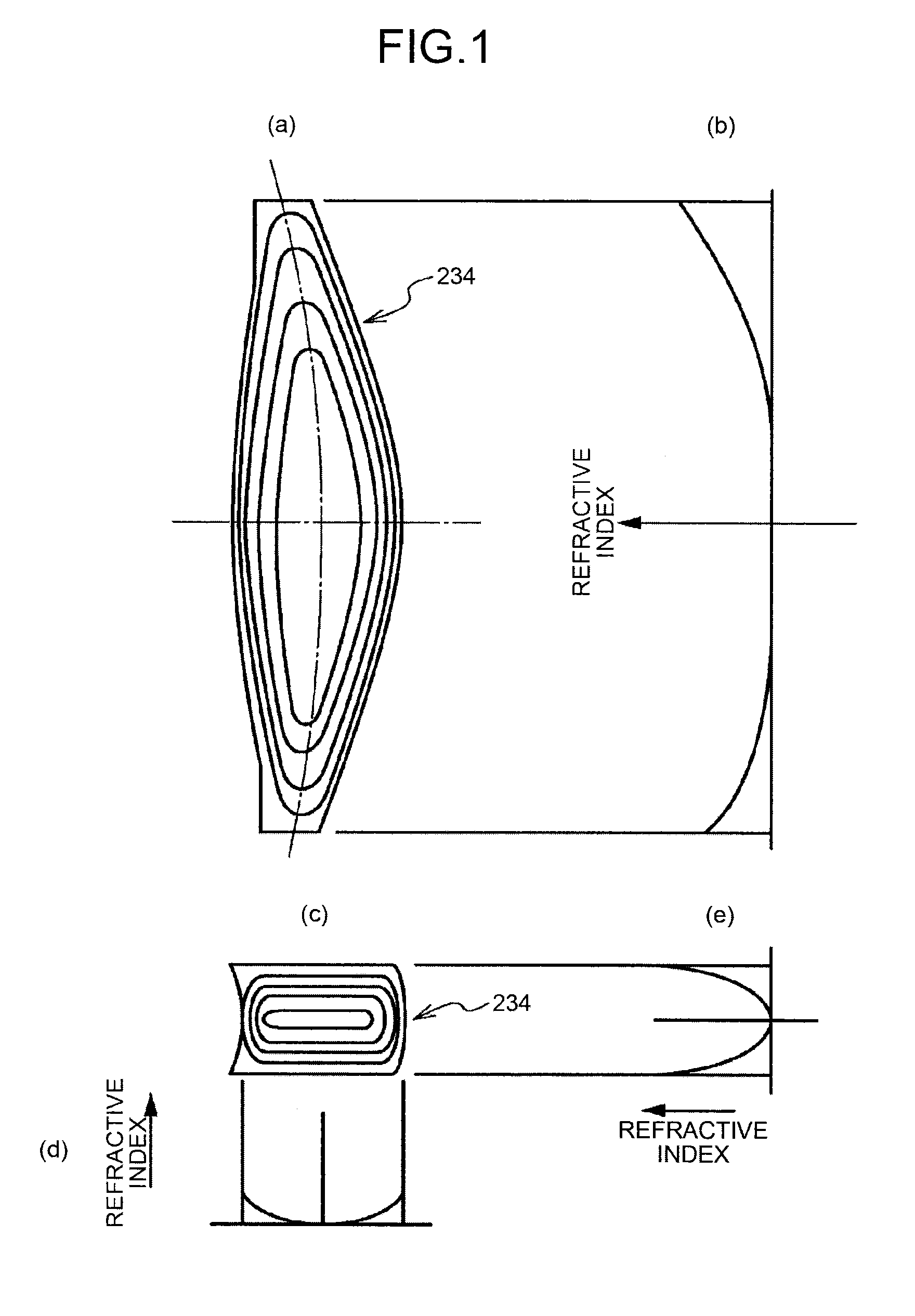
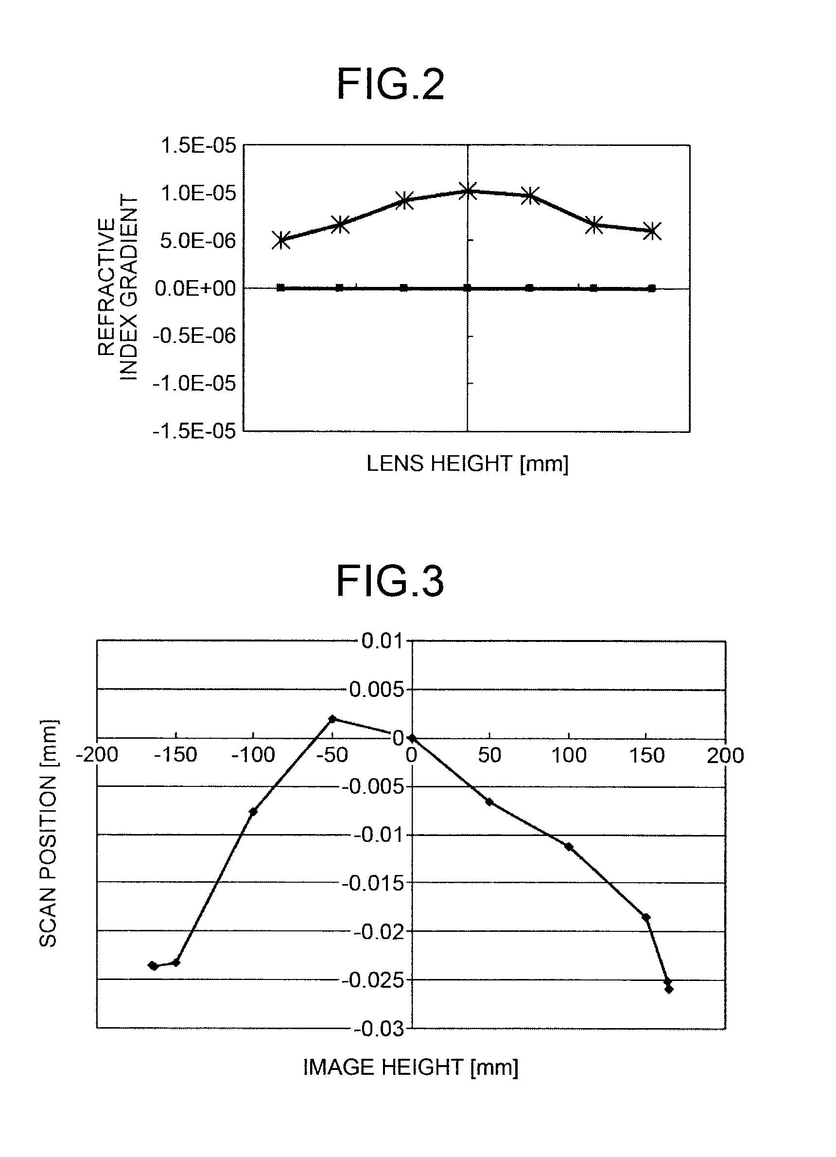
[0051]The scanning lens 234 of a first implementation example has such a refractive index gradient as that illustrated in FIG. 2. However, because the special surface is applied to the scanning lens 234, scan line bow resulting from the refractive index gradient is corrected. Meanwhile, it is possible to correct scan line bow by tilt-decentering a lens surface in the sub-scanning direction. tilt-decentering angle of this tilt-decentered surface is set in such a manner that the tilt-decentering angle increases from a portion near the center of the scanning lens 234 to outer periphery of the scanning lens 234, or vice versa. In the present invention, as illustrated in FIG. 6, scan position in the sub-scanning direction is corrected for each image height by balancing scan positions among across image heights, thereby correcting scan line bow on the scanned surface.

[0052]The special surface is further described below. The surface shape of the special surface is expressed by Shape Equati...

second implementation example

[0062]In the first implementation example described above, the special surface is implemented by tilt-decentering each of the surfaces of the scanning lens. In contrast, in a second implementation example, the special surface is implemented by shift decentering. As will be described later, the scan line bow correction can be achieved by shift decentering the special surface of the scanning lens 234.

[0063]In the second implementation example, the special surface is shift decentered in such a manner that a shift-decentering distance in the sub-scanning direction varies in the main-scanning direction, so that the direction of light beam varies in the sub-scanning direction. This special surface can be obtained by providing coefficients to d00, d01, and d02 of Equation (1) described above.

[0064]FIG. 8 is a diagram for illustrating relation between a shift-decentering distance and a change of a light beam in the sub-scanning direction. FIG. 8(a) illustrates a case where the scanning lens...

third implementation example

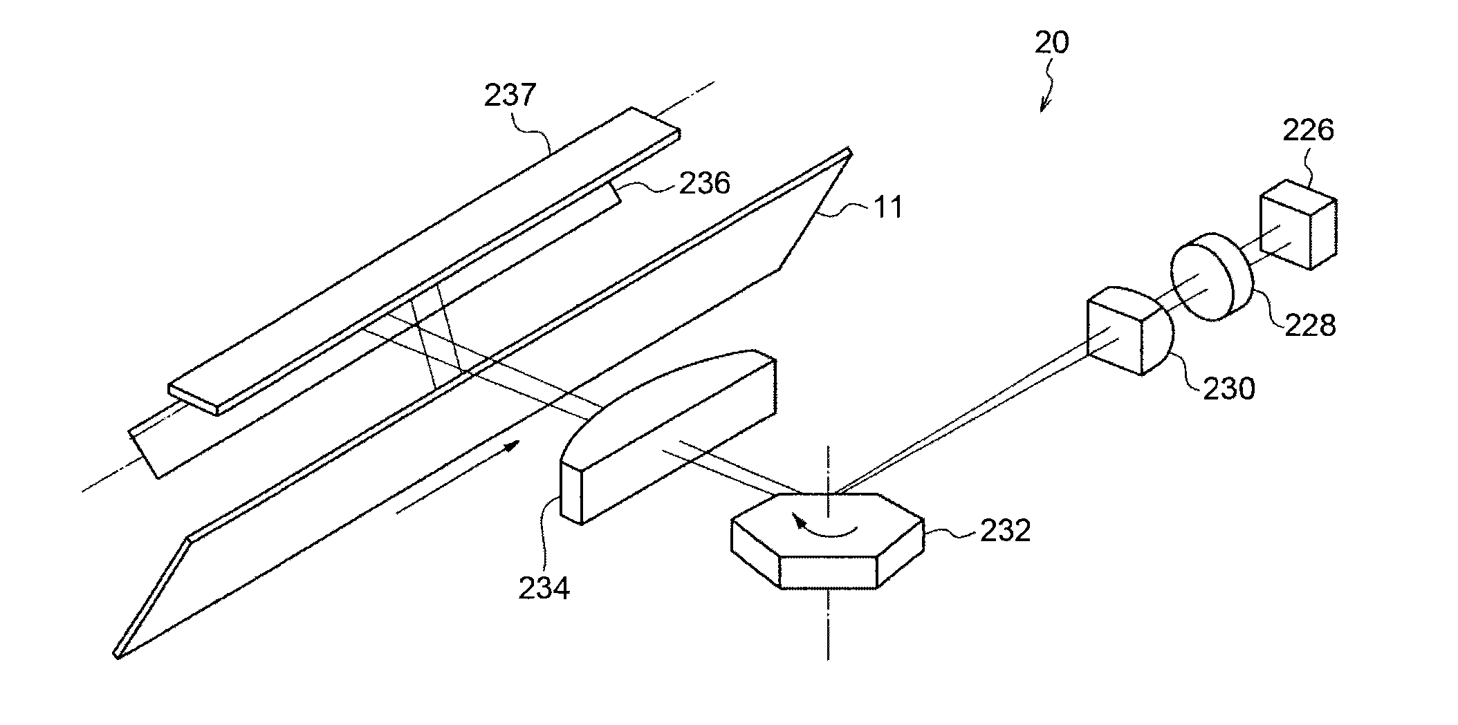
[0066]As illustrated in FIG. 9, the optical scanning device according the embodiments may be configured such that a plurality of light source units emit light beams that strike the deflective reflection facet obliquely in the sub-scanning direction with respect to the normal of the deflective reflection facet of the light deflector 232 to be reflected from the deflective reflection facet. Employment of such what is referred to as an oblique incidence optical system allows reducing the width of the light deflector, which forms a large proportion in cost among components of the optical scanning device, as compared with a configuration in which light beams parallel to the normal strike the light deflector 232. Accordingly, such an oblique incidence optical system is effective in cost reduction of the optical scanning device.

[0067]The light beams emitted from the plurality of light source units (not shown) obliquely strike a same deflective reflection facet of the same light deflector 2...


PUM


Abstract

An optical device includes: a light source that emits a light beam; a deflector that deflects the light beam in a main-scanning direction; and a scanning / image-forming optical system that includes a scanning lens that causes the light beam deflected by the deflector to converge to a scanned surface to form an image on the scanned surface. The scanning lens has refractive index gradient. At least one surface of the scanning lens is a tilt-decentered surface that has a tilt angle, which depends on a position in the main-scanning direction, in a sub-scanning direction. The tilt angle is set so as to compensate for variation, which results from the refractive index gradient, in direction of the light beam in the sub-scanning direction.

Description

CROSS-REFERENCE TO RELATED APPLICATIONS[0001]The present application claims priority to and incorporates by reference the entire contents of Japanese Patent Application No. 2012-054775 filed in Japan on Mar. 12, 2012.BACKGROUND OF THE INVENTION[0002]1. Field of the Invention[0003]The present invention relates to an optical scanning device and an image forming apparatus.[0004]2. Description of the Related Art[0005]From a viewpoint of cost reduction of an optical scanning device, a scanning lens, which is one of optical elements that make up the optical scanning device, forms a large proportion of the cost. Cost of the scanning lens chiefly depends on length of time necessary for molding the scanning lens. Put another way, the shorter the molding time, the less the cost. Meanwhile, molding of a scanning lens is typically performed by injecting heated and softened resin into a molding die and fill the die with the resin. During this molding, refractive index gradient that depends on th...

Claims


Application Information

Patent Timeline
IPC IPC(8): B41J2/435G02B26/08
CPCG03G15/04036G02B26/10G03G15/0435G02B3/0087G02B26/125G02B13/0005
Inventor MIYAKE, SHINSUKEIMAI, SHIGEAKI
Owner RICOH KK
Why Eureka
Try Eureka