Multi-fiber connector with ferrule float

a multi-fiber connector and ferrule technology, applied in the field of multi-fiber connectors, can solve the problem that the flat support surface does not allow the ferrule to float, and achieve the effect of facilitating the movement of the ferrul

Active Publication Date: 2013-09-12
TYCO ELECTRONICS LOGISTICS AG (CH)
View PDF4 Cites 9 Cited by
  • Summary
  • Abstract
  • Description
  • Claims
  • Application Information

AI Technical Summary

Benefits of technology

[0007]The present invention provides a connector configuration that facilitates movement of the ferrule relative to the rest of the connector to compensate for manufacturing anomalies, particularly at the end face of the ferrule. Specifically, in a traditional connector, the ferrule is supported by a flat surface of a retainer plate. The flat support surface does not allow the ferrule to float sufficiently to align and compress the fibers to ensure physical contact between them. However, the connector of the present invention uses one or more beveled / curved surfaces between the retainer and the ferrule to enable the ferrule to move relative to the retainer (and thus the rest of the connector). Allowing the ferrule to float during mating enables it to move as needed to achieve proper optical coupling between all the fibers. This results in consistent RL performance across the fiber paths.

Problems solved by technology

The flat support surface does not allow the ferrule to float sufficiently to align and compress the fibers to ensure physical contact between them.

Method used


Image

  • Multi-fiber connector with ferrule float
  • Multi-fiber connector with ferrule float
  • Multi-fiber connector with ferrule float

Examples


Embodiment Construction

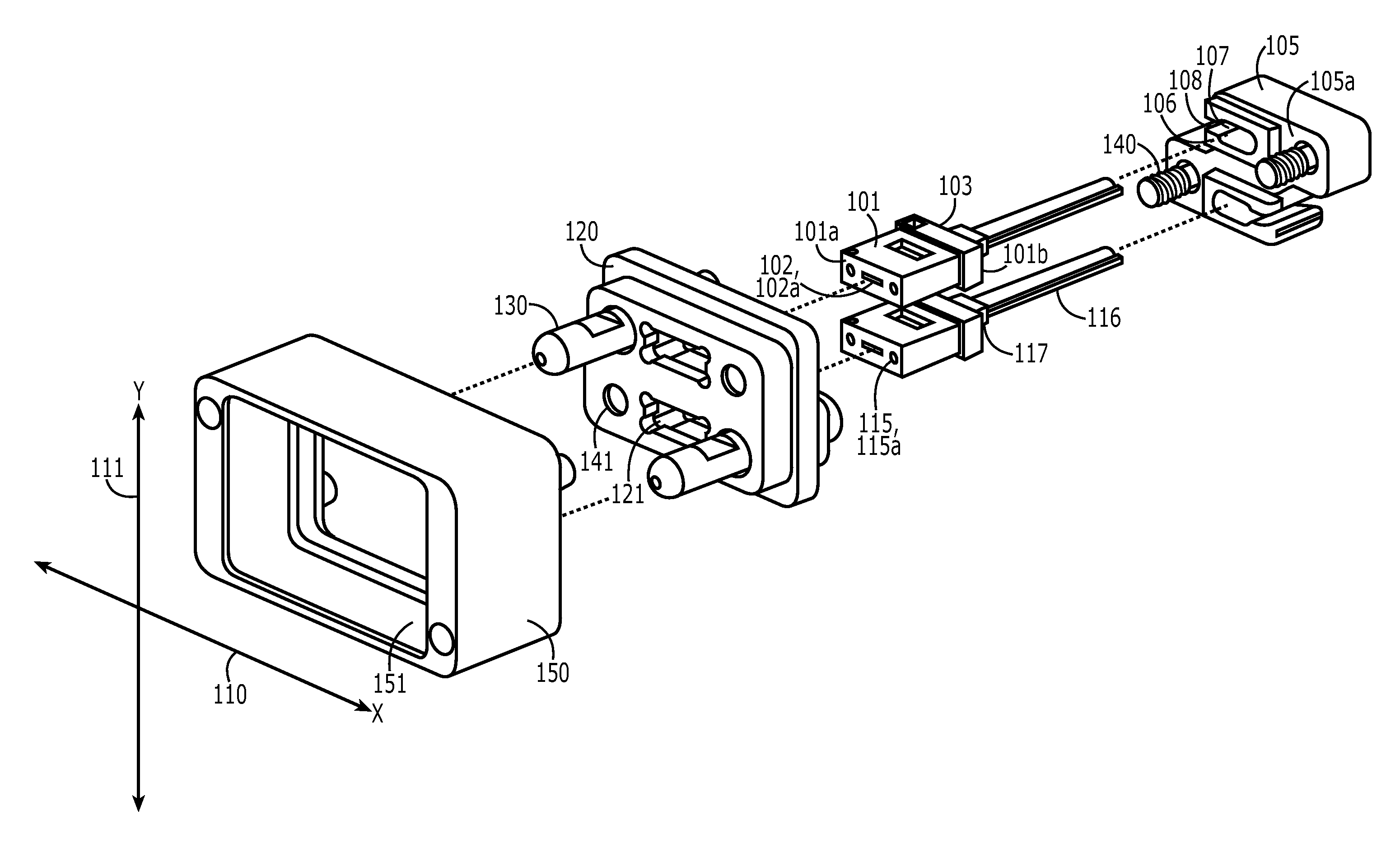
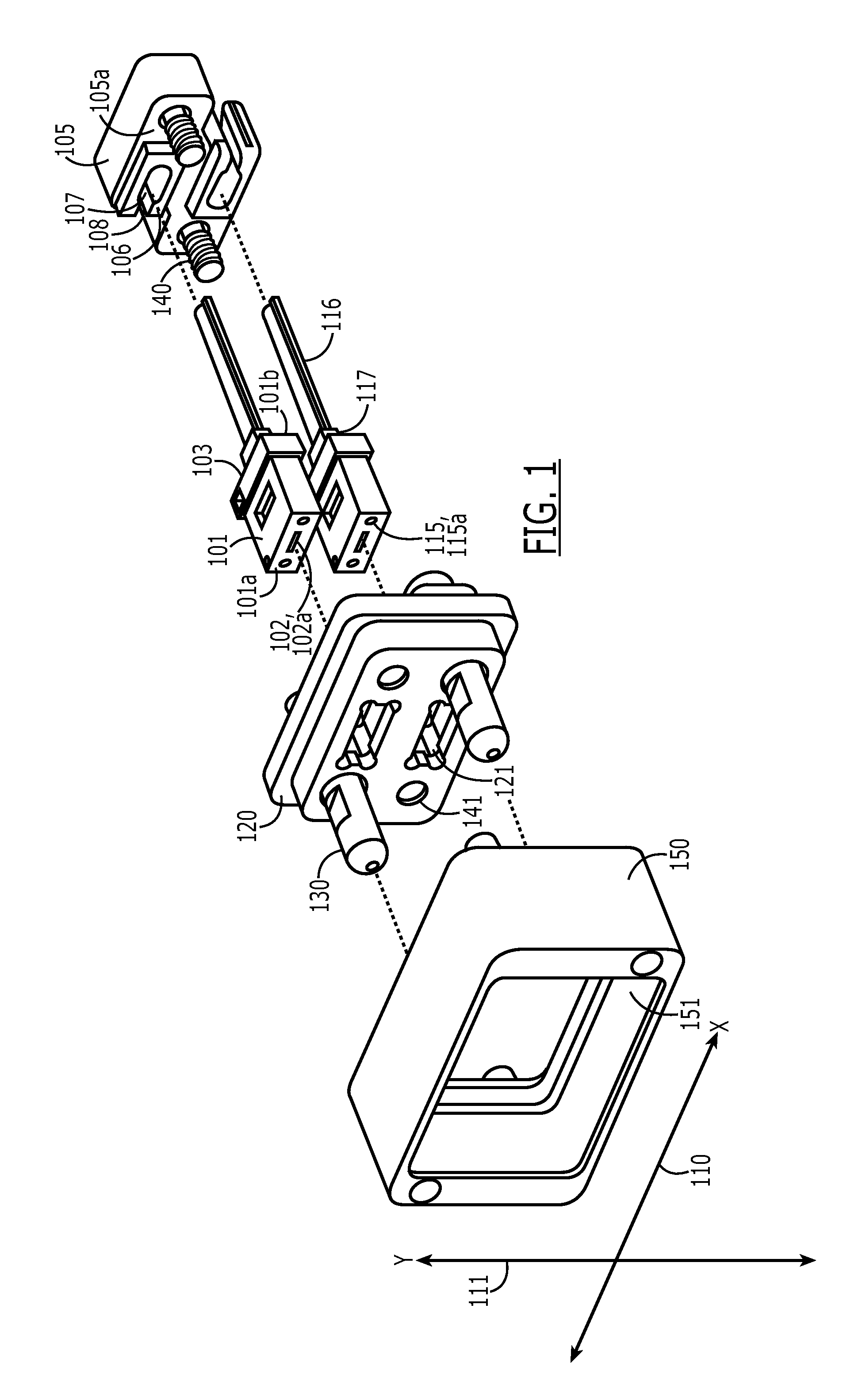
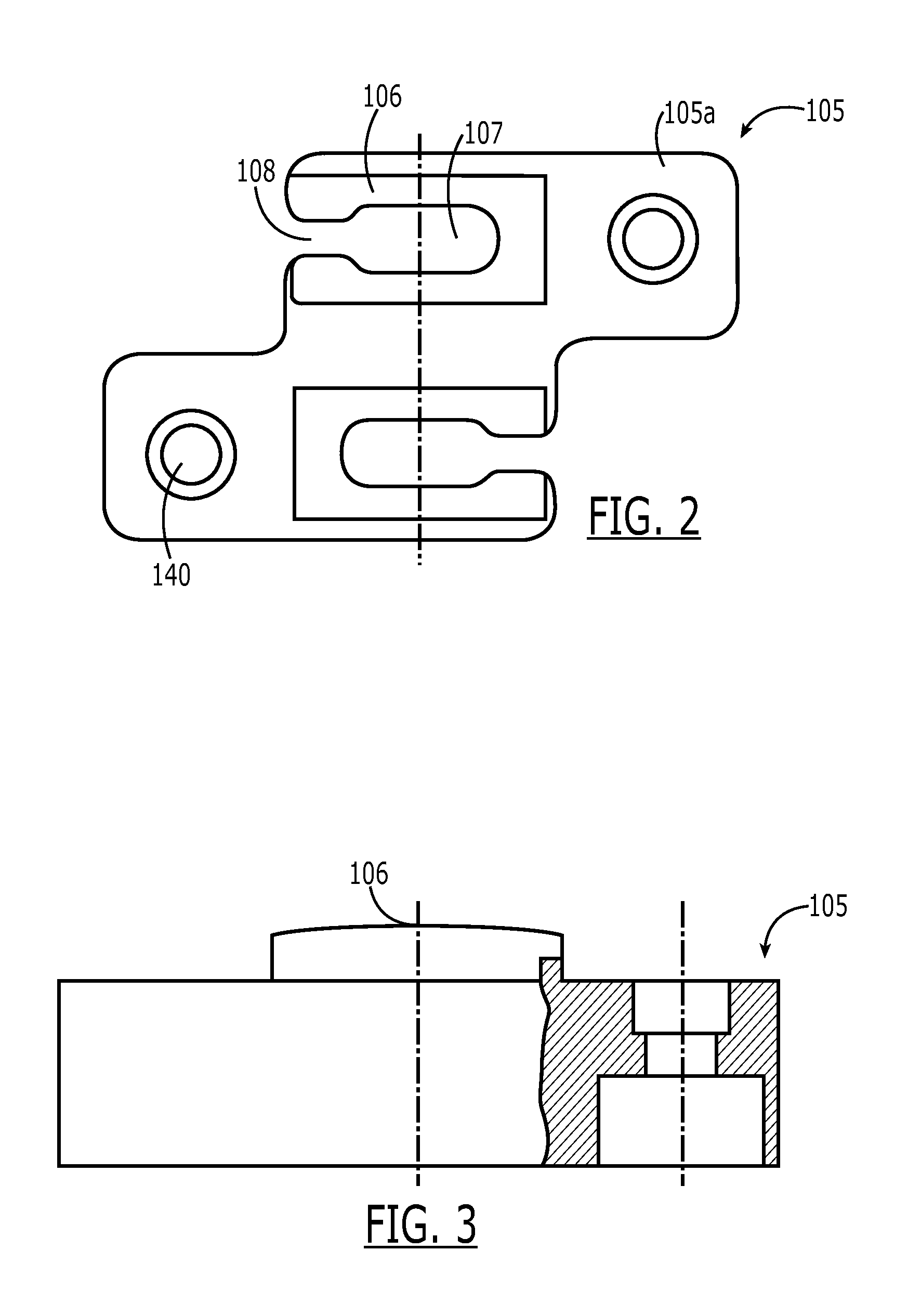
[0014]Referring to FIG. 1, one embodiment of the connector 100 of the present invention is shown. The connector 100 comprises at least one multi-fiber ferrule 101 having a front face 101a presenting a plurality of end faces 102a of fibers 102, and a back face 101b having a first surface 103 and defining a first orifice (not shown) through which fibers 102 pass. The connector also comprises a retainer 105 for supporting the multi-fiber ferrule 101. The retainer comprises a front face 105a having a second surface 106 and defining a second orifice 107 through which the fibers pass. The second surface 106 contacts the first surface 103 to provide a backstop for the ferrule 101. At least one of the first surface 103 or second surface106 is beveled / curved along at least one of an x-axis 110 or a y-axis 111 such that the multi-fiber ferrule 101 is able to move relative to the retainer about at least one of the axes. Each of these elements is considered in greater detail below.

[0015]The fer...


PUM


Abstract

A connector comprising: (a) at least one multi-fiber ferrule having a front face presenting a plurality of fiber end faces, and a back face having a first surface and defining a first orifice through which the fibers pass; (b) a retainer for holding the at least one multi-fiber ferrule, the retainer comprising a front face having a second surface and defining a second orifice through which the fibers pass, the second surface contacting the first surface; wherein at least one of the first or second surface is convex along at least one of an x-axis or a y-axis such that the at least one multi-fiber ferrule is able to move relative to the retainer about at least one of the axes.

Description

FIELD OF INVENTION[0001]The present invention relates generally to multi-fiber connectors, and, more specifically, to multi-fiber connectors with ferrule float to compensate for manufacturing anomalies and other alignment issues.BACKGROUND OF INVENTION[0002]Optical fiber connectors are a critical part of essentially all optical fiber communication systems. For instance, such connectors are used to join segments of fiber into longer lengths, to connect fiber to active devices, such as radiation sources, detectors and repeaters, and to connect fiber to passive devices, such as switches, multiplexers, and attenuators. The principal function of an optical fiber connector is to hold the fiber end such that the fiber's core is aligned with an optical pathway of the mating structure. This way, light from the fiber is optically coupled to the optical pathway.[0003]Of particular interest herein are backplane connector systems. Backplane connector systems are well known, and typically compris...

Claims


Application Information

Patent Timeline
Patent Type & Authority Applications(United States)
IPC IPC(8): G02B6/36
CPCG02B6/3821G02B6/3885G02B6/3878
Inventor FABIAN, DAVID JAMESFULPONI, JOHN ANTHONYHEBERLE, RONALD PATRICKMOSIER, JAMES PATRICK
Owner TYCO ELECTRONICS LOGISTICS AG (CH)
Why Eureka
Try Eureka