Electrical junction box

a junction box and junction box technology, applied in the direction of coupling device details, coupling device connection, printed circuits, etc., can solve the problems of difficult to ensure that sufficient fixing force always is obtained, difficult to secure sufficient surface area, complex structure, etc., to improve the degree of freedom in the design of the connector lock, the effect of excellent guiding

Inactive Publication Date: 2013-09-12
SUMITOMO WIRING SYST LTD
View PDF0 Cites 12 Cited by
  • Summary
  • Abstract
  • Description
  • Claims
  • Application Information

AI Technical Summary

Benefits of technology

[0013]A guiding groove may be formed on an inner face of the receptacle for each connector housing and may be aligned for guiding a connector housing in an insertion / removal direction. A guiding groove in the gap may be formed over the entire length of the inner face in the insertion / removal direction of the connector housing. Thus, all of the connector housings may be guided independently, thereby making it possible to guide the stacked connector stably regardless of the number of connector housings that are stacked. More particularly, the connector locks are formed on the second case. Thus, the shape of the opening portion of the receptacle may be set without giving consideration to the connector lock, and the guiding grooves may be formed corresponding to all of the connector housings. Furthermore, guiding grooves in portions that do not contact the connector locks are formed over the entire length of the inner face to achieve an excellent guiding effect.
[0014]The connector lock on the second case may be a projection that projects toward the first case. A latching catch for latching a connector housing may be on a tip of the connector lock and may extend from outside the first case into the receptacle via an aperture in a side wall of the first case. Accordingly, the receptacle can be formed with better space utilization compared, for example, to a structure in which a through-hole for insertion of the connector lock is formed in the bottom wall of the first case, and the connector lock is positioned inside the receptacle via the through-hole. Outward flexure deformation of the connector lock is not restricted. Thus, a sufficient amount of flexure can be obtained, and a secure fixing force is achieved based on restoring force from the flexure deformation.
[0015]In the present invention, the receptacle is formed in the first case, while the connector locks are provided on the second case. Thus, the degree of freedom in the design of the connector locks is improved, and the size of the connector locks can be large enough to latch at least two connector housings so that the stacked connector can be fixed more stably.

Problems solved by technology

Accordingly, it is not possible to secure sufficient surface area of engagement between the connector locks and the stacked connector, and it is difficult to ensure that sufficient fixing force always is obtained.
However, this structure becomes complex and costly.

Method used


Image

  • Electrical junction box
  • Electrical junction box
  • Electrical junction box

Examples


Embodiment Construction

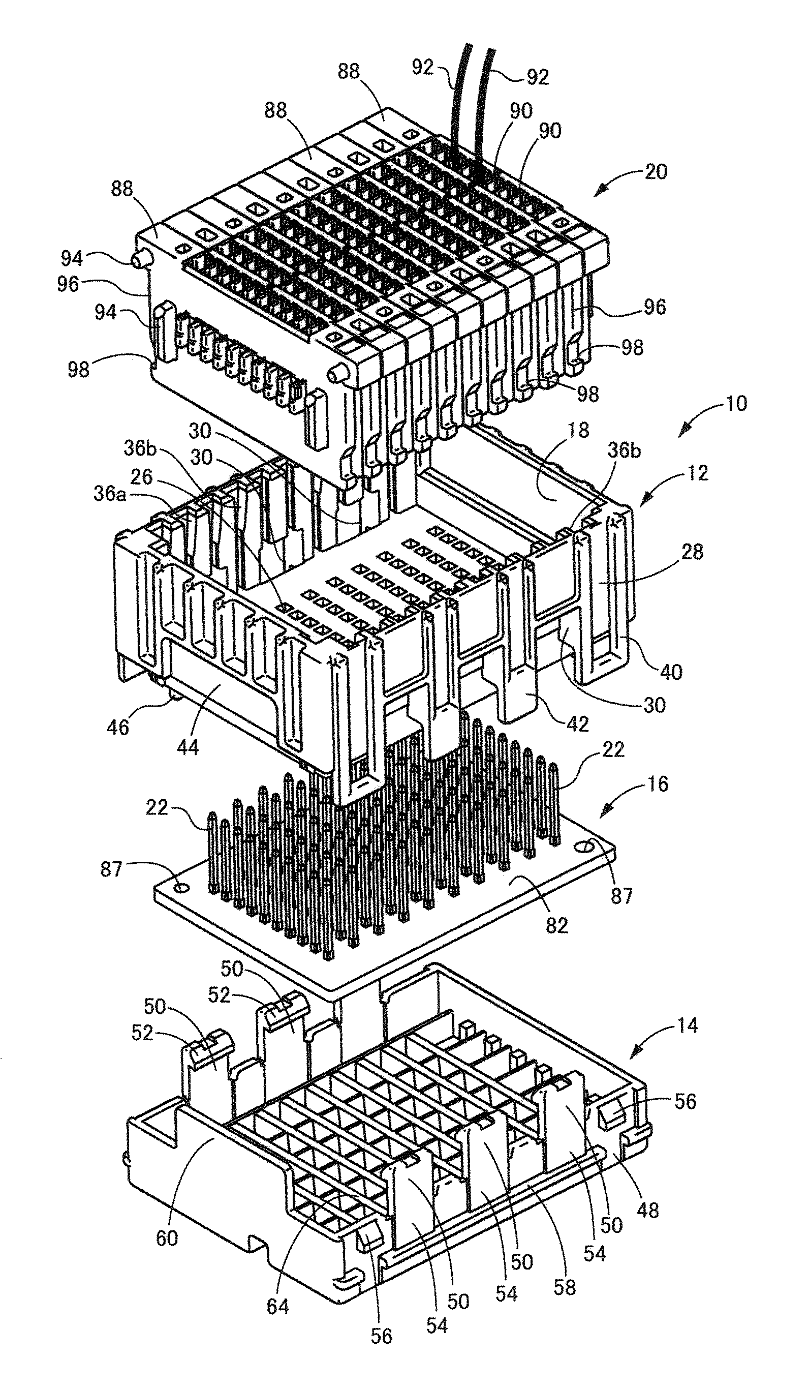
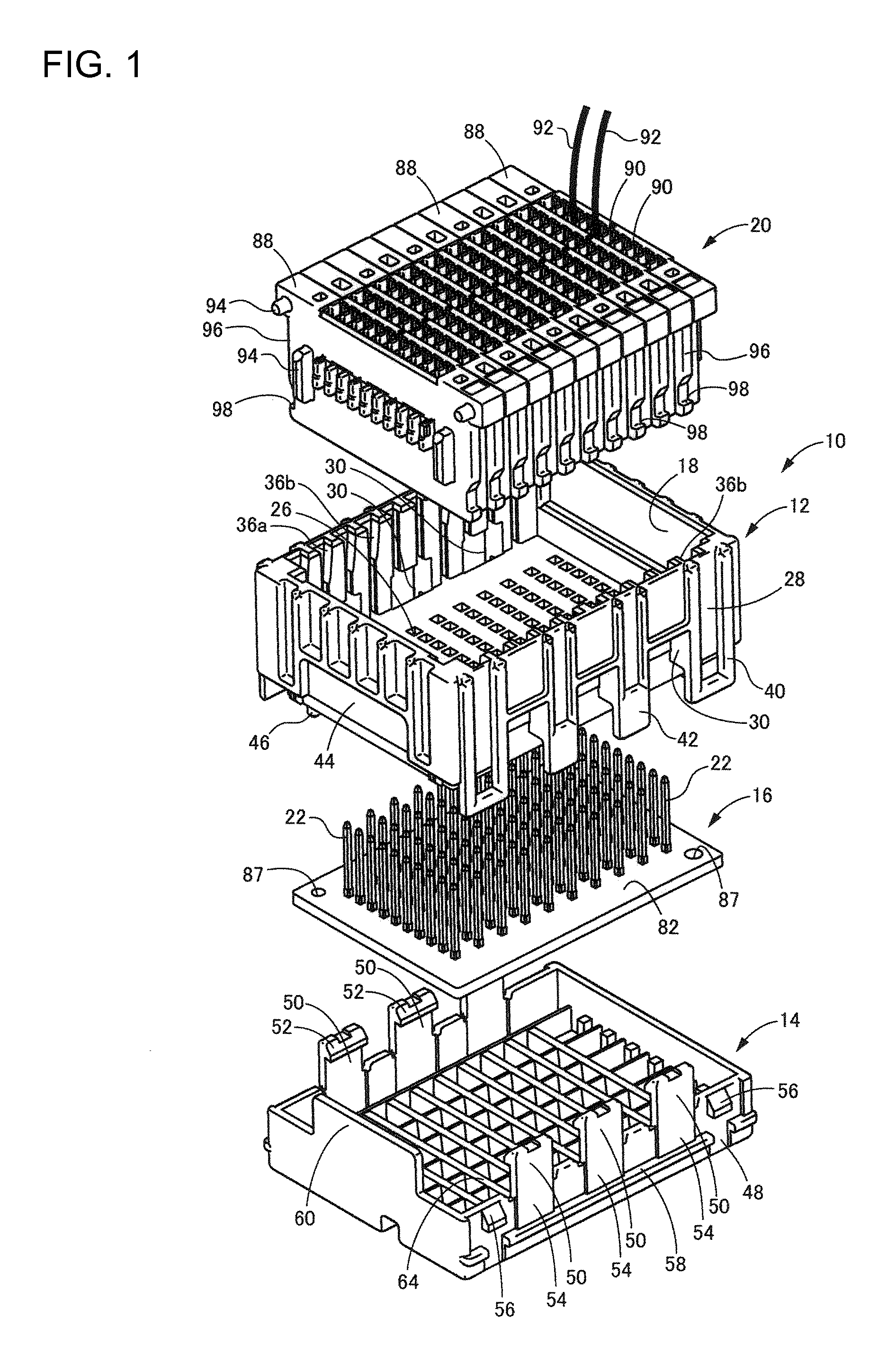
[0030]FIG. 1 shows an electrical junction box 10 according to a first embodiment of the invention. The electrical junction box 10 has a circuit board 16 housed between a first or upper case 12 and a second or lower case 14. A stacked connector 20 is housed in a receptacle 18 in the upper case 12 and can be connected to connection terminals 22 projecting from the circuit board 16. The terms upper and lower are used herein to refer to the orientation shown in FIG. 1.

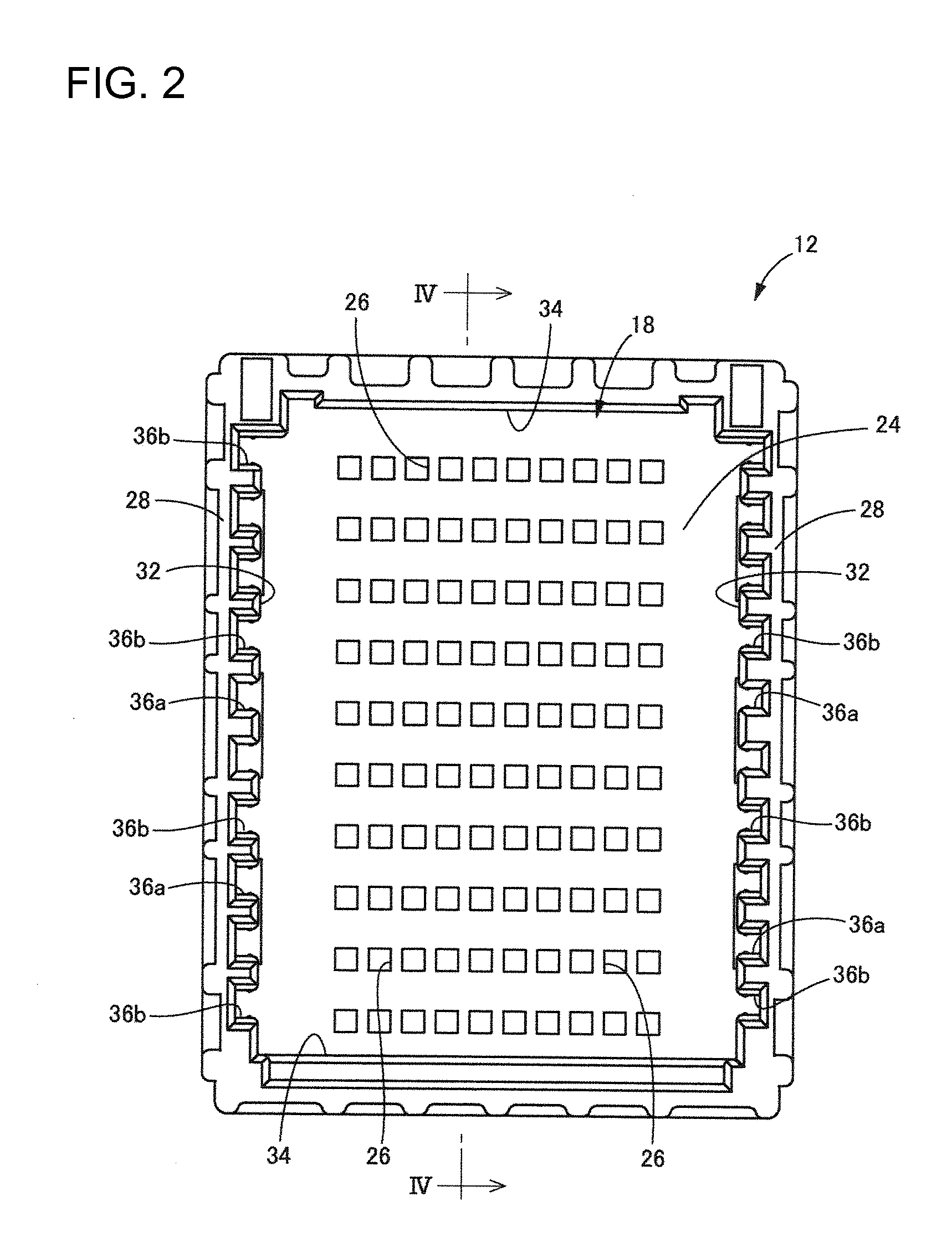
[0031]FIGS. 2 to 4 show the upper case 12. The upper case 12 is molded unitarily from synthetic resin to define a substantially elongated rectangular box that is open at the top. The receptacle 18 is a substantially rectangular void in the open top of the upper case 12.

[0032]The upper case 12 has a bottom wall 24 at the bottom of the receptacle 18 and terminal insertion holes 26 are formed in the bottom wall 24. In the present embodiment, ten terminal insertion holes 26 are formed in a row and are separated by a constant g...


PUM


Abstract

An electrical junction box has a box body (84) is formed by combining a first case (12) and a second case (14). The first case (12) has a receptacle (18) for housing a stacked connector (20). A connector lock (50) is provided on the second case (14) for fixing the stacked connector (20) inside the receptacle (18). The connector lock (50) latches and fixes at least two of the connector housings (88) that are successive in the stacking direction in the stacked connector (20).

Description

BACKGROUND OF THE INVENTION[0001]1. Field of the Invention[0002]The invention relates to an electrical junction box for an automobile or the like, and in particular an electrical junction box for connection with a stacked connector obtained by stacking multiple connector housings.[0003]2. Description of the Related Art[0004]Electrical junction boxes typically are used in automobiles and the like to facilitate the branching of wiring harnesses and connect wiring harnesses to electrical components such as fuses and relays. The electrical junction box typically has a circuit board housed inside a box body configured by combining upper and lower cases. Connection terminals project from the circuit board and into a receptacle in the box body. Connectors provided at the terminals of wiring harnesses then are inserted into the receptacle and connect to the connection terminals of the circuit board.[0005]U.S. Pat. No. 7,594,830 discloses an electrical junction box that is intended to accomm...

Claims


Application Information

Patent Timeline
Patent Type & Authority Applications(United States)
IPC IPC(8): H01R9/22
CPCH01R13/506H01R13/514H01R9/223H01R2201/26H01R13/6273
Inventor KATSUSE, SHUNSUKE
Owner SUMITOMO WIRING SYST LTD
Why Eureka
Try Eureka